
Installation Instruction

9
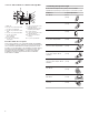
13. Using a
1
/
4
" nut driver, screw the electrical junction cover
to the burner box with 2 screws.
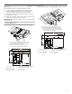
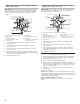
Install Foam Strip
1. Remove foam strip from the package containing literature.
2. Remove backing from foam strip.
3. Remove 1 of the 4 foam strips.
4. Apply foam strip adhesive-side down around bottom of
cooktop,
1
/
4
" (6.4 mm) from edge and cut out excessive
material
1
/
4
" (6.4 mm) from edge.
NOTE: The foam strip keeps the underside of the cooktop
glass free from debris and helps the cooktop sit flat on
uneven counters.
5. Repeat steps 3 and 4 for remaining edges.
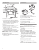
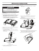
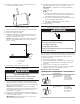
Install Cooktop
1. Using 2 or more people, lift the cooktop from packaging
foam and install the cooktop into the countertop cutout by
tilting one end of the cooktop into the cutout, then lowering
the other end into the cutout.
NOTE: Make sure that the front edge of the cooktop is
parallel to the front edge of the countertop. If repositioning
is needed, lift entire cooktop up from cutout to avoid
scratching the countertop.
2. Rotate motor to align with duct work and attach ducting.
3. Fully tighten motor and, using a
1
/
4
" nut driver, reattach motor
access cover with 2 screws.
IMPORTANT: Verify that the motor access cover is fully
tightened and back on the plenum.
4. Using a wood block between the screw and the countertop,
moderately tighten the screws to secure the cooktop.
IMPORTANT: Do not tighten screws directly against the
countertop.
5. Install grease filter.
NOTES:
■ The filter should always be placed at an angle. As you
face the front of the cooktop, the top of the filter should
rest against the right side of the vent opening.
■ The bottom of the filter should rest against the left side
of the vent chamber at the bottom.
■ If the filter is flat against the fan wall, ventilation
effectiveness will be reduced.
6. Install vent grille.
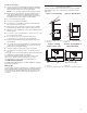
Make Electrical Connection
This cooktop is manufactured with the frame connected to the
bare ground wire. Connect the cooktop cable to the junction box
through the UL Listed or CSA Approved conduit connector.
1. Disconnect power.
2. Remove junction box cover, if present.
3. Connect the flexible cable conduit from the cooktop to the
junction box using a UL Listed or CSA Approved conduit
connector.
4. Tighten screws on conduit connector if present.
5. See the “Electrical Connection Options” chart to complete
installation for your type of electrical connection.
Electrical Connection Options
If your home has: And you will be
connecting to:
Go to Section:
4-wire A fused disconnect
or circuit breaker
box
4-Wire Cable
from Home
Power Supply
to 4-Wire Cable
from Cooktop
½"
(1.3 cm)
3-wire A fused disconnect
or circuit breaker
box
3-Wire Cable
from Home
Power Supply
to 4-Wire Cable
from Cooktop -
U.S. only
½"
(1.3 cm)
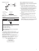
A
B
C
1/4"
(6.4 mm)
A. Cooktop base
B. Foam strip
C. Glass
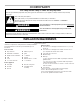
WARNING
Excessive Weight Hazard
Use two or more people to move and install cooktop.
Failure to do so can result in back or other injury.
WARNING
Electrical Shock Hazard
Disconnect power before servicing.
Use 8 gauge copper wire.
Electrically ground cooktop.
Failure to follow these instructions can result in death,
fire, or electrical shock.