
Instruction Sheet


9
4. For LP gas conversion:
Completely tighten screw “C” to set the minimum flame
height.
For Natural gas conversion:
Tighten screw “C” to reduce flame height. Loosen screw to
increase flame height. See “Complete Burner Adjustment”
section.
5. Replace the control knob.
6. Test the flame by turning the control from LO to HI, checking
the flame at each setting.
Adjustment for Dual Valve
To Adjust Inner Crown Flame:
1. Set the inner crown flame to LO.
2. Remove the control knob.
3. Remove the black rubber grommet.
4. Using needle-nose pliers, remove the gray shield inside the
burner valve opening.
5. For LP gas conversion:
Completely tighten screw “A” to set the minimum flame
height.
For Natural gas conversion:
Tighten screw “A” to reduce flame height. Loosen screw to
increase flame height. See “Complete Burner Adjustment”
section.
6. Replace the control knob.
To Adjust Outer Crown Flame:
1. Set the outer crown flame to LO.
2. Remove the control knob.
3. For LP gas conversion:
Completely tighten screw “B” to set the minimum flame
height.
For Natural gas conversion:
Tighten screw “B” to reduce flame height. Loosen screw to
increase flame height. See “Complete Burner Adjustment”
section.
4. Replace the gray shield. Use a screwdriver to help push the
shield into place.
5. Replace the black rubber grommet.
6. Replace the control knob.
7. Test the flame by turning the control from LO to HI, checking
the flame at each setting.
Complete Burner Adjustment
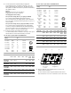
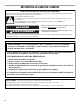
1. Check burner flame(s) for a proper size and shape. The
cooktop low burner flame should be a steady blue flame
approximately ¹⁄₄" (0.64 cm) high.
2. Completely fill out the conversion label and attach label to
bottom of the cooktop next to the rating tag. Do not cover the
rating tag with the conversion label.
IMPORTANT: Place gas orifice spuds in plastic parts bag for
future use and keep with package containing literature.
Read “Sealed Surface Burners” section in the Use and Care
Guide supplied with your cooktop.
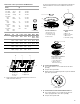
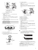
A.
³⁄₃₂
" (#0 [2.0 mm]) flat-blade screwdriver
(screwdriver shaft must be a minimum of
2" [5.1 cm] long)
B. Control knob stem opening
C. Adjustment screw location
A. Inner crown
B. Outer crown
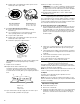
A. Control knob
B. Black rubber grommet
C. Gray shield
B
C
A
A
B
M
e
d
A
B
C
A. Inner crown adjustment screw
B. Outer crown adjustment screw
A. Low flame
B. High flame
B
A
A
B