
Operation Manual


Change Grill Main Burner Valve Orifices
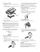
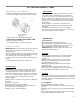
1. Remove the grates and flame tamers.
2. Remove the 1 screw (A) and cotter clip (B) that hold the
burner in place. Set the screw and clip aside. Remove the
burner from the grill by lifting the burner out.
1. A combination of pipe fittings must be used to connect
the grill to the existing gas line.
The 10 ft (3.0 m) PVC flexible gas supply hose design
certified by CSA must be used.
Pipe-joint compounds suitable for use with Natural gas
must be used Do not use Teflon®+ tape
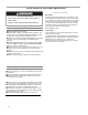
Make Gas Connection
B
must
be
used
.
Do
not
use
Teflon®+
tape
.
There must be a certified manual shut-off valve on the
gas supply line near the grill for easy access.
2. Use a pipe wrench to connect the brass connector on
one end of the 10 ft (3.0 m) PVC flexible gas supply hose
to the Natural gas pressure regulator.
3. Connect the quick connector on the other end of the 10
ft
(
3.0 m
)
PVC flexible
g
as su
pp
l
y
hose to the ri
g
id
A
A. Screw
B Cotter Clip
() gppy g
Natural gas supply pipe. To use the quick connect fitting;
pull the head of the quick connect back, insert the end of
the PVC gas hose and release the head of the connector.
Check the connection and make sure it is secure.
A
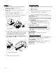
3. Use a 6 mm socket and wrench or 6 mm nut driver to
remove the LP brass orifice from the end of each gas
valve. The NG orifice is located behind the LP orifice, so
no additional orifice needs to be installed.
B
.
Cotter
Clip
B
D
C
A. Main burner orifice
A
† ®Teflon is a registered trademark of E.I. Du Pont De
Nemours and Company.
A. Manifold
B. Right side panel
C.10 ft. (3.0 m) PVC gas hose
D. Natural gas pressure regulator/hose assembly
IMPORTANT: Check that the orifice is properly installed
inside of the burner opening.
4. Reinsert the burner and reattach using the screw and
cotter clip previously removed. Repeat the procedure
for each main burner.
5. Position the igniters so they are 1/4" (6.0 mm) away
from each burner.
21