
Cooktop User Manual

Electrical
requirements
Installation
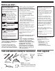
Excessive Weight Hazard
Use two or more people to move
and install cooktop.
Failure to do so could result in
back or other injury.
WARNING
6
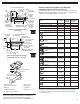
The downdraft cooktop must be
connected to the proper electrical voltage
and frequency as specified on the
model/serial rating plate. The model/serial
rating plate is located on the bottom of the
cooktop.
A four-wire or three-wire, single-phase,
240-volt, 60-Hz, AC-only electrical
supply is required on a separate
30-ampere circuit, fused on both sides
of the line.
A time-delay fuse or circuit breaker is
recommended. The fuse size must not
exceed the circuit rating of the
appliance as specified on the
model/serial rating plate.
CONNECT WITH COPPER WIRE
ONLY.
Connected directly to the fused
disconnect (or circuit breaker box)
through flexible, armored or non-
metallic sheathed, copper cable (with
ground wire).
Flexible armored cable should connect
cooktop directly to the junction box.
Fuse both sides of the line.
Locate the junction box to allow as
much slack as possible between the
junction box and cooktop so that the
downdraft cooktop can be moved if
servicing is ever necessary.
A U.L.-listed 1/2" (12.7 mm) conduit
connector must be provided at the
junction box.
The recommended minimum copper
wire size is No.-10 gauge. However,
wire sizes and connections must conform
to the requirements of the National
Electrical Code, ANSI/NFPA 70 — latest
edition*, or CSA Standards C22.1-94,
Canadian Electrical Code, Part 1 and 22.2
No. 0-M91 - latest edition** and all local
codes and ordinances. Wire sizes and
connections must conform with the rating
of the cooktop.
Copies of the standard listed may be obtained from:
* National Fire Protection Association
Batterymarch Park
Quincy, Massachusetts 02269
** Canadian Standard Association
178 Rexdale Boulevard
Etobicoke, Ontario M9W 1R3
The wiring diagram is located on the
bottom of the cooktop.
Twist-on connectors and U.L.-listed 1/2"
(12.7 mm) conduit connector are not
provided.
If codes permit and a separate ground
wire is used, it is recommended that a
qualified electrician determine that the
ground path is adequate.
Do Not ground to a gas pipe.
Check with a qualified electrician if you
are not sure cooktop is properly
grounded.
Do Not have a fuse in the neutral or
grounding circuit.
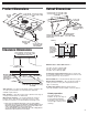
1. Remove shipping materials and tape
from cooktop.
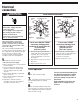
2. The blower is set to vent straight out
the back of the cooktop.
To vent to the left side, right side or down
through the bottom of the cabinet, add an
elbow to the blower assembly exhaust vent.
It may be easier to connect appliance
cable to junction box before inserting
cooktop into cutout. See “Electrical
connections,” Page 7.
3. Insert downdraft cooktop into cutout.
Check that:
cooktop is centered in cutout.
front edge of downdraft cooktop is at least
1-1/2" (38.1 mm) from front edge of
countertop and parallel to countertop.
rear edge of cooktop is at least 3/4"
(19.1 mm) from rear wall as recommended.
side edge of cooktop is at least 6 inches
(15.2 cm) from side wall.
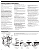
Lift entire cooktop up from cutout
when positioning cooktop in
countertop opening.
4. Connect vent system. See “Venting
requirements,” Pages 4-5. Use duct tape to
seal all joints. Vent must end with a wall or roof
cap outside the building.