
Range - Freestanding Range User Manual


Important: Observe all
governlng codes and
ordinances.
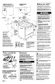
Check location where range will be
installed. The range should be
located for convenient use in kitchen.
ALL OPENINGS IN THE WALL OR
FLOOR WHERE RANGE IS TO BE
INSTALLED MUST BE SEALED.
13” max.
upper
cabinet
+- depth
Before you start...
Proper installation is your responsibility. A
qualified technician should install this range.
Make sure you have everything necessary for
correct installation. It is the responsibility of the
installer to comply with installation clearances
specified on the serial/rating plate. The
serial/rating plate is located on the oven frame
behind
the oven door.
~13” max
upper
cabinet ~
depth
For minimum
clearance,
Personal Injury Hazard
Avoid installing cabinet storage above
the cooking surface. If cabinets are
already Installed, reduce the hazard of
reaching over a heated cooking surface
by Installing a range hood. The range
hood should extend a minimum of 5
inches out from the bottom front of the
cabinets.
Reaching over a heated cooking surface
could result in a serious burn or other
personal injury.
Electrical Shock Hazard
It is the customer’s responsibility:
l
To contact a qualified electrical
installer.
l
To assure that the electrical installation
Is adequate and in conformance with
National Electrical Code, ANSVNFPA
70-latest edition**, and all local codes
and ordinances.
Failure to do so could result in fire,
electrical shock or other personal injury.
4” Min.
. . see “:r-
counrenop 1
.
18” min. clearance
30-3/8”
upper cabinet to
countertop.
openlng
I
/ wldth
Wall
receptacle -
6” to 22” fron
elther cablne
7” max. from
floor.
o Not pinch
18 power
+y
I
I
36”
I
countertop
helght
I
I //-
I ///’
I ., ’
\
Grounded electricil\ ,
cord between
the ran e and
outlet is reauired.
\
the wal ? .
\
L
Mobile home installation
The installation of this range must conform to
the Manufactured Home Construction and
Safety Standards, Title 24 CFR, Part 3280
(formerly the Federal Standard for Mobile
Home Construction and Safety, Title 24, HUD,
Part 280); or when such standard is not
applicable, the Standard for Manufactured
Homes Installations 1982 (Manufactured Home
Sites, Communities and Setups), ANSI A2251 -
1987, or latest edition*‘, or with local codes.
When this range is installed in a mobile home,
it must be secured to the floor during transit.
Any method of securing the range is adequate
as long as it conforms to the standards listed
above.
See Electric’al
requirements.
\
\
/ I
Do Not seal
\
\
the range to
\
the slde
cabinets.
.
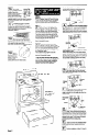
NOTE: Clearances
specified are for
combustible walls
and materials that have
-JY
a density of 20 or more
pounds per cubic foot. No
evaluation of clearances has
been made for installations
adjacent to materials that are
less than 20 pounds per cu. ft.
or to plastic tile or sheeting.
Cablnet opening dimensions that
are shown must be used. Given
dimensions are minimum clearances
and provide required 0” clearance.
t
Four-wire power supply cable must be used in
a mobile home installation. The appliance
wiring will need to be revised. See 4-wire
electrical connection, Panel C.
Copies of the standards listed may be obtained
from:
**National Fire Protection Association
Batterymarch Park
Quincy, Massachusetts 02269
*Note: 24” mln. when bottom of wood
or metal cabinet Is protected by not
less than 114” flame retardant
mlllboard covered wlth not less than
No. 26 MSG sheet steel, 0.015”
stalnless steel, 0.024” alumlnum or
0.020” copper.
30” mln. clearance between the top
of the cooklng platform and the
bottom of an unprotected wood or
metal cabinet.
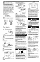
The an&tip
bracket MUST
be Installed. For
detalled
lnstructlons.
see Panels B
and C.
Tools needed for Electrical
installation:
requirements
(A/
. A three-wire or a four-wire single phase,
120/240-volt, 60-Hz, AC-only, electrical
supply (or three-wire or four-wire 120/208-volt if
specified on serial plate) is required on a
separate 40-ampere circuit, fused on both sides
of the line. A time-delay fuse or circuit breaker is
recommended.
Save Installation Instructions for the
local electrical inspector’s use.
Power cord is not supplied but is
available through you local electrical
supply houses.
THE RANGE MUST BE CONNECTED
WITH COPPER WIRE ONLY.
/c.(
Electrlcal Shock Hazard
. Electrical ground is required on thls
appliance.
l
Improper connection of the equipment-
grounding conductor can result in
electrical shock.
l
Check with a qualified electrician if you
are in doubt as to whether the appliance
is properly grounded.
l
Only a power supply cord kit rated at 250
volts, 40 amperes and investigated for
use with ranges should be used.
l
Do Not have a fuse in the neutral or
grounding circuit. A fuse in the neutral or
grounding circuit could result in electrical
shock.
l
Do Not plug the “pigtail” power cord into a
live wall receptacle before the cord Is
permanently connected to the terminal
block. To do so may result in personal
injury from electrical shock.
Failure to follow these instructions could
result in a fire, electrical shock or personal
injury.
Local codes may permit the use of a
U.L.-listed, 250-volt, 40-ampere range
power supply cord (pigtail). This cord’ contains
three, No.-1 0 copper wires and matches a three-
wire receptacle of NEMA Type 1 O-50R, shown in
Figure 1. Connectors on the appliance end must
be ring terminals. A U.L.-listed strain relief must
be provided at the point the power supply cord
enters the appliance.
hand or electric drill
wood/metal wall stud:
l/B-Inch drill blt
concrete/concrete block walls:
3116.Inch carblde-tlpped
masonry drill blt
ID.I
The appliance should be connected
directly to the fused disconnect or
- circuit breaker box through flexible,
armored or non-metallic sheathed, copper
cable. Allow two or three feet of slack in the
line so that it can be moved if servicing is ever
necessary.
A U.L.-listed conduit connector must be
provided at each end of the power supply
cable (at the appliance and at the junction
box). Wire sizes (COPPER WIRE ONLY) and
connections must conform with the rating of
the appliance (40 amperes).
Parts supplied for
installation:
2 screws (#lo x l-112”)
(Thickness of wall coverln may
9
requlre longer screws, ava lable
from you local hardware store.)
:ket
2 plastic anchors
Panel A