
Installation Guide


21
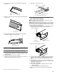
3. Remove one end cap by loosening the nuts and sliding the
end cap off.
4. Slide the custom panel into the top grille channel and reattach
the end cap.
5. Replace the top grille in the cabinet side trims and pull the
panel down slightly to lock it into place.
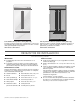
Adjust Door(s)
Door Alignment (36" [91.4 cm] Single-Door Models)
1. Loosen, but do not remove, the four Torx
®†
27 flat-head
mounting screws and the two ¹⁄₄" hex-head mounting screws
in the top hinge.
2. Adjust the top hinge of the door to align it.
3. Tighten the Torx
®†
27 flat-head mounting screws to a torque of
approximately 100 inch-pounds (11.3 Nm).
4. Tighten the ¹⁄₄" hex-head screws.
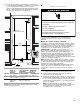
Door Height Adjustment (36" [91.4 cm] and 42"
[106.7 cm] French Door Models)
Use the following steps to adjust the door height, up or down,
after the refrigerator has been leveled.
NOTE: Adjust the right-hand door to the position of the left-hand
door first. If it is necessary to adjust the left-hand door, you must
make sure that the hinged center rail located on the left-hand door
does not drag when closing the door.
1. Open the freezer drawer. Remove the locking plate screw from
the bottom side of the refrigerator door hinge using a
¹⁄₄" open-end wrench.
2. Remove the locking plate as shown.
3. Turn the bushing located underneath the bottom of the hinge
using a ¹⁄₂" open-end wrench. Turning the bushing to the left
will lower the door. Turning the bushing right will raise the
door.
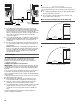
4. After adjusting, check the doors to make sure they are even at
the top and bottom. If the doors are not even, continue to turn
the bushing to adjust the door.
5. Replace the locking plate.
■ Turn the bushing slightly to align the hinge and locking
plate screw holes.
■ Replace and tighten the locking plate screw.
6. Make final check to make sure the doors are aligned and
even.
A. Bottom rail
B. Nuts
C. End cap
D. Top rail
A. Custom panel
A. Top grille
B. Cabinet side trims
C
B
A
D
A
B BA
†®TORX is a registered trademark of Saturn Fasteners, Inc.
A. Torx
®†
27 flat-head mounting screws
B.
¹⁄₄
" hex-head mounting screws
A. Bushing
B. Locking plate
C. Locking plate screw
A
B
BCA