
Installation Instructions
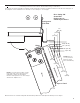
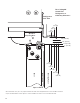

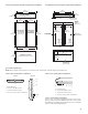
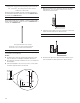
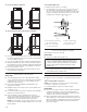
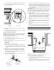
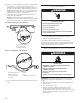
Table Of Contents
- REFRIGERATOR SAFETY
- MODELS
- INSTALLATION REQUIREMENTS
- Tools and Parts
- Location Requirements
- Electrical Requirements
- Water Supply Requirements
- Tipping Radius
- Product Dimensions
- Door Swing Dimensions
- Overlay Series Door Panel and Cabinetry Clearance
- Custom Overlay Panel Dimensions
- Overlay Series Custom Panels
- Stainless Steel and Overlay Series Both 36" and 42" models have the same cabinet side trim
- INSTALLATION INSTRUCTIONS
- Unpack the Refrigerator
- Reduce Tipping Radius (if required)
- Move the Refrigerator into House
- Install Anti-Tip Boards
- Connect the Water Supply
- Plug in Refrigerator
- Move Refrigerator to Final Location
- Level and Align Refrigerator
- Install Overlay Custom Panels
- Adjust Door(s)
- Install Side Panel
- Install Base Grille
- Complete Installation
- SÉCURITÉ DU RÉFRIGÉRATEUR
- MODÈLES
- EXIGENCES D’INSTALLATION
- Outils et pièces
- Exigences d’emplacement
- Spécifications électriques
- Spécifications de l’alimentation en eau
- Rayon de basculement
- Dimensions du produit
- Dimensions pour l’ouverture des portes
- Dégagement des panneaux de porte de série Overlay et des armoires
- Panneaux personnalisés de série Overlay
- Dimensions des panneaux personnalisés
- Les modèles de série Overlay et en acier inoxydable de 36" et 42" sont dotés de la même garniture latérale de caisse
- INSTRUCTIONS D’INSTALLATION
- Déballage du réfrigérateur
- Réduire le rayon de basculement (le cas échéant)
- Déplacement du réfrigérateur dans le domicile
- Installation de planches antibasculement
- Raccordement à la canalisation d’eau
- Brancher le réfrigérateur
- Déplacement du réfrigérateur à son emplacement définitif
- Réglage de l’aplomb et alignement du réfrigérateur
- Installation des panneaux personnalisés Overlay
- Ajustement des portes
- Installation du panneau latéral
- Installation de la grille de la base
- Terminer l’installation

18
36" (91.4 cm) Single Door Models
36" (91.4 cm) and 42" (106.7 cm) French Door Models
2. Place pieces of the shipping carton on the oor when rolling
the dolly and refrigerator into the house. Move the refrigerator
close to the built-in opening.
3. Place top of cardboard carton or plywood under refrigerator.
4. Stand the refrigerator up. First, place the left bottom edge of
the refrigerator on the oor, stand the refrigerator upright and
then lower the right-hand side of the refrigerator to the oor.
5. Do not remove lm or cover.
6. Reassemble the trim and top grille after the dolly has been
removed from the refrigerator.
Install Anti-Tip Boards
IMPORTANT:
■ To avoid tipping during use, the solid soft must be within
1" (2.5 cm) maximum above the refrigerator. If the solid soft
is higher than 1" (2.5 cm) or one is not available, then the
refrigerator must be braced.
■ It is recommended that board(s) be installed before the
refrigerator is installed.
■ Board(s) must be long enough to fully cover the width of the
compressor cover.
■ Locate the board(s) so the bottom surface(s) of the board(s) is
(are) 84" (213 cm) from the oor.
■ During installation, raise the refrigerator up so there is
1/4" (0.64 cm) maximum between the top of the refrigerator
and the bottom of the anti-tip board(s). Do not crush the
compressor cover when raising the rear leveling legs.
NOTE: The foam gasket, on top of the compressor cover, will
compress to t under the anti-tip board(s). There is no need to
trim the gasket.
To Install Anti-tip Boards
1. Mark the stud locations on rear wall.
2. Securely attach one or two 2" x 4" x 32" (5 cm x 10 cm x
81 cm) boards to wall studs behind refrigerator. Use six
#8 x 3" (7.6 cm) (or longer) wood screws. The wood screws
must be screwed into the studs at least 1½" (3.8 cm). The
board(s) must overlap the compressor cover.
Connect the Water Supply
Read all directions before you begin.
IMPORTANT:
■ Connect to potable water supply only.
■ If you turn the refrigerator on before the water line is
connected, turn the ice maker OFF.
Connect to Water Line
Parts Needed
■ Minimum 7 ft (2.13 m) exible, codes-approved water supply
line
Style 1—Shutoff Valve Connection
NOTE: If your water line connection does not look like Style 1,
see “Style 2—Copper Line Connection.”
1. Unplug refrigerator or disconnect power supply.
IMPORTANT:
■ There is not enough clearance to achieve a ush installation
if a water shutoff valve is located in the wall behind the
refrigerator. The water shutoff should be located in the base
cabinet on either side of the refrigerator.
■ Before attaching the tubing to shutoff valve, ush the main
water supply line to remove particles and air in the water line.
Allow enough ow so that water becomes clear. Flushing the
water line may help avoid lters and/or water valves from
becoming clogged.
BA
C
D
A. Center board 1/4" (6.35 mm)
max. above refrigerator
B. Two 2" x 4" x 32" (5 cm x
10 cm x 81 cm) boards
C. Attach to studs with six
#8 x 3" (7.6 cm) screws
D. Compressor cover
Do not use with water that is microbiologically unsafe or
of unknown quality without adequate disinfection before
or after the system. Systems certified for cyst reduction
may be used on disinfected waters that may contain
filterable cysts.
2"
(5 cm)