Instructions de montage
Indications importantes concernant la sécurité 4 Pour la sécurité des enfants 4 Caractéristiques de l'appareil et exigences d'installation 5 Caractéristiques de la niche d’installation: built-in 6 Caractéristiques de la niche d’installation: integrated 7 Préparation à l’installation 8 Raccordements électrique et hydraulique 9 Mise à niveau 10 Préparation des panneaux décoratifs pour la porte et Grands bacs - built-in 11 Prédisposition panneaux de décoration pour réfrigérateur - built-in 1
Indications importantes concernant la sécurité Symboles utilisés dans le manuel Important Indications afin d’éviter tout endommagement de l’appareil Note conseils pour une correcte utilisation de l’appareil Attention indications afin d’éviter toute lésion aux personnes Pour la sécurité des enfants Si cet appareil remplace un autre appareil déjà existant qui doit être mis de côté ou éliminé, veiller à ce que celui-ci ne devienne pas un dangereux piège pour les enfants, en coupant le câble d’alimentation et
Caractéristiques de l'appareil et exigences d'installation Dimensions appareil Built-in/Integrated 60 cm : l : 587 mm (23 1/8” in) / h : 2050 mm (80 3/4” in) / p : 575 mm (22 5/8” in) 75 cm : l : 737 mm (29” in) / h : 2050 mm (80 3/4” in) / p : 575 mm (22 5/8” in) 90 cm : l : 887 mm (35” in) / h : 2050 mm (80 3/4” in) / p : 575 mm (22 5/8” in) Dimensions emballage Built-in/Integrated 60 cm : l : 650 mm (25 5/8” in) / h : 2210 mm (87” in) / p : 800 mm (31 1/2” in) 75 cm : l : 800 mm (31 1/2” in) / h : 2210 m
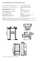
Caractéristiques de la niche d’installation: built-in A: espace à réserver aux équerres anti-renversement 75cm : 1285 mm (50 5/8" in) 60cm : 1135 mm ( 44 3/4" in) Angle d’ouverture de la porte 105° Largeur 90cm : 899 mm (35 3/8" in) 75cm : 749 mm (29 1/2" in) 60cm : 599 mm (23 5/8" in) Hauteur 2050 mm (80 3/4" in) ± 25 mm (1" in) Profondeur (sans panneau) 575 mm (22 5/8” in) E: espace à réserver au passage du câble W: d’alimentation et au tuyau d’alimentation de l’eau Hauteur minimale de l’encastrement 20
Caractéristiques de la niche d’installation: integrated A: espace à réserver aux équerres anti-renversement 75cm : 1285 mm (50 5/8" in) 60cm : 1135 mm ( 44 3/4" in) Angle d’ouverture de la porte 105° Largeur 90cm : 899 mm (35 3/8" in) 75cm : 749 mm (29 1/2" in) 60cm : 599 mm (23 5/8" in) Hauteur 2050 mm (80 3/4" in) ± 25 mm (1" in) Profondeur 600 mm (23 3/4” in) E: espace à réserver au passage du câble W: d’alimentation et au tuyau d’alimentation de l’eau Hauteur minimale de l’encastrement 2064 mm (81 1/4
Préparation à l’installation Transport sur le lieu d’installation et déballage S’agissant d’un appareil lourd et de grandes dimensions, avant de transporter l’appareil, s’informer sur les modalités d’accès au lieu où il sera installé (dimensions des portes, espaces de mouvement dans les escaliers, etc.). L’appareil est fixé à la base de l’emballage (palette) moyennant quatre boulons amovibles avec une clé de 17 mm (3/4” in).
Raccordements électrique et hydraulique Pour le branchement électrique prévoir une prise Schuko de 16A ou une prise UK de 13A munie de mise à la terre ou contrôlée par un interrupteur omnipolaire facilement accessible. Pour le raccordement hydraulique (pour les appareils équipés de fabricateur de glace) il faut prévoir un robinet avec raccord mâle de ¾”, facilement accessible même lorsque l’appareil est installé.
Raccordements électrique et hydraulique Arrière de l’appareil Branchement Électrique Raccordement Hydraulique Intervenir de la manière suivante: • Dérouler le câble électrique et le brancher directement à la prise murale. • Contrôler que l’appareil soit en stand-by et que les voyants soient éteints; dans le cas contraire, appuyer sur la touche Unit pour éteindre l’appareil. • Raccorder le tuyau de l’eau au réfrigérateur dans la zone arrière 1.
Préparation des panneaux décoratifs pour la porte et Grands bacs - built-in Les dimensions des panneaux sont indiquées dans le tableau et sur les dessins reportés ci-dessous. Selon les exigences d’alignement avec d’autres meubles de la cuisine, le panneau de la porte du réfrigérateur peut être plus haut par rapport à la ligne supérieure de la porte et le panneau inférieur peut être plus bas par rapport à la ligne inférieure du grand bac.
Préparation des panneaux décoratifs pour la porte et Grands bacs - built-in • Vérifier la position des trous en appuyant les équerres sur les marques 4 puis pratiquer les trous en faisant attention à l’épaisseur du panneau 5. • Visser les équerres 6.
Prédisposition panneaux de décoration pour réfrigérateur - built-in 90cm 75cm 60cm Charnière Gauche Charnière Droite Charnière Gauche Charnière Droite Charnière Gauche Charnière Droite A 897 (35 1⁄4”) 897 (35 1⁄4”) 747 (29 3/8”) 747 (29 3/8”) 597 (23 1/2”) 597 (23 1/2”) B 355,5 (14”) 261 (10 1/4”) 279 (11”) 187 (7 3⁄8”) 205 (8 1⁄8”) 111 (4 3⁄8”) C 261 (10 1/4”) 355,5 (14”) 187 (7 3⁄8”) 279 (11”) 111 (4 3⁄8”) 205 (8 1⁄8”) D 418 (16 1/2”) 386 (15 1/4”) 343 (13 1⁄2”) 311 (12 1
Prédisposition panneaux de décoration pour réfrigérateur avec porte en verre - built-in 90cm 60cm Charnière Gauche Charnière Droite Charnière Gauche Charnière Droite A 897 (35 3⁄8”) 897 (35 3⁄8”) 597 (23 1/2”) 597 (23 1/2”) D 418 (16 1/2”) 386 (15 1/4”) 276,5 (10 7⁄8”) 236,5 (9 3⁄8”) E 386 (15 1/4”) 418 (16 1/2”) 236,5 (9 3⁄8”) 276,5 (10 7⁄8”) F/G 354,5 (14”) 354,5 (14”) 203,5 (8”) 203,5 (8”) H 417 (16 3/8”) 384 (15 1/8”) 275 (10 7⁄8”) 235 (9 1⁄4”) I 384 (15 1/8”) 417 (16 3/
Dimensions panneaux - built-in Séries Largeur de la porte et de tiroir A Porte: Largeur de la coupure B 90cm 897 (35 1/4”) 627 (24 3/4”) 75cm 747 (29 3/8”) 60cm 597 (23 1/2”) 327 (12 7/8”) Exemples de calcul Intégration dans une colonne cuisine avec une hauteur total de 2160 mm (85” in) et plinthe de 150 mm (6” in). (NOTE: dans le calcul du pied de réglage est considéré à 0).
Fixation des panneaux à la porte et au Grand bac - built-in Aprés avoir appliqué les pattes de fixation et les équerres aux panneaux, commencer l’installation par le tiroir du bas. Intervenir de la manière suivante: • Serrer les vis que partiellement aux fixations inférieures 1. • Fixer le panneau aux support du tiroir à partir des crans de la partie inférieure de réglage 2.
Fixation des panneaux à la porte et au Grand bac - built-in • Accrocher le panneau aux dispositifs de fixation en insérant dans les crans d’alignement supérieurs 6. • Il est possible d’ajuster l’alignement du panneau par rapport aux meubles adjacents à l’aide des pattes et des équerres d’alignement 7 et 8. • Alignement vertical: soulever ou abaisser le panneau 9 en vissant ou en dévissant la vis à l’équerre.
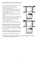
Installation dans la niche Encastrement appareil unique Des profils en aluminium peuvent être utilisés pour fermer les espaces entre l’appareil et les meubles adjacents ou un autre appareil juxtaposé à celui-ci. Intervenir de la manière suivante: • Pousser l’appareil dans la niche d’installation 1. • Si l’appareil doit être installé dans une niche ou à l’intérieur d’une structure fermée, il sera nécessaire de prévoir une cheminée de ventilation à l’arrière de la niche pour garantir une ventilation adèquate.
Installation dans la niche Encastrement combinaison Accessoires nécessaires à commander séparément: • Kit raccordement central Des profils en aluminium peuvent être utilisés pour fermer les espaces entre l’appareil et les meubles adjacents ou un autre appareil juxtaposé à celui-ci. Intervenir de la manière suivante: • Positionner les appareils devant la niche en laissant un espace suffisant pour intervenir sur l’arrière des appareils 1.
Installation dans la niche • Une fois complétés les passages ci-dessus, poussez les appareils dans leur position définitive 6. Il sera nécessaire de prévoir une cheminée de ventilation à l’arrière de la niche pour garantir une ventilation adèquate. Un écart de 5 mm est suffisant pour éviter tout surchauffement. Assemblez toujours les panneaux frontaux à la porte et aux tiroirs avant de placer l’appareil dans sa position définitive dans la niche ou la structure.
Installation dans la niche Combinaison libre installation Accessoires nécessaires à commander séparément: • Kit raccordement central • Kit Freestanding Des profils en aluminium peuvent être utilisés pour fermer les espaces entre l'appareil et les meubles adjacents ou un autre appareil juxtaposé à celui-ci. Intervenir de la manière suivante: • Positionner les appareils devant la niche en laissant un espace suffisant pour intervenir sur l'arrière des appareils.
Installation dans la niche 7 • Fixer les panneaux latéraux à l’appareil, en les assemblant aux profiles latéraux 7 prémontés sur l’ensemble. • Joindre la couverture en aluminium 8 à chaque profil lateral, en appuyant jusqu’au “click”. 8 • Assemblez le panneau du haut 9 au dessus de l’appareil, en utilisant les vis fournies. • Reglez la hauteur de l’ensemble avec les pieds de réglage et les roues postérieures.
Montage de la sécurité anti-renversement Afin d’éviter le risque de renversement de l’appareil lors de l’ouverture de la porte et des bacs à pleine charge, l’installation de deux équerres qui fixent la partie supérieure de l’appareil au mur est obligatoire. Intervenir de la manière suivante: • Les équerres sont appliquées comme illustré à la figure en utilisant les vis et les chevilles fournies.
Ventilation Un système à air forcé assure la ventilation à travers la grille positionnée dans la dans la partie inférieure de l’appareil. Si l’aménagement de la cuisine prévoit une plinthe, cette dernière doit être trouée afin de garder un niveau d’aréation satisfaisant, comme expliqué dans le dessin. Les trous peuvent être de toute sorte de forme et dimension, à condition que la surface totale de la partie trouée est égale au 50% de la surface de la plinthe.
Contrôle de fin d’installation mise en marche • Contrôler que les pieds sont correctement installés. • Contrôler que le raccordement à l’installation hydrique ne présente pas de fuites d’eau et que le robinet de fermeture est facilement accessible. • Contrôler que le branchement électrique soit correctement réalisé et que la fiche et l’interrupteur omnipolaire dédié soient facilement accessibles. • Contrôler le parfait alignement de l’appareil avec les meubles adjacents.
Printed in Italy r 09/16 400011025861 FR