
Installation guide


3
front
screws
(4
rear
screws
required
but not
shown)
attaching
the
backguard
attaching
the
island
trim
center
hole
not
used
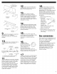
9
u
Attach
the
backguard
or
island
trim
as
required
for
your
installation.
Attachment
screws
are
in
the
literature
package.
1
0
w
Slide
range
completely
back
so
anti-tip
bracket
is
over
rear
brace
of
range.
use
pipe-joint
compound
regulator
flexible
/
cgnmecto
\
4/2
tan
4/2"
to
3/4"
gas
union
adapter
pipe
a
1/2"
male
pipe
thread
is
needed
for
connection
to
pressure
regulator
female
pipe
threads
manual
gas
shutoff
valve
1 1
a
Make
gas
connection.
Assemble
flexible
connector
from
gas
supply
pipe
to
pressure
regulator
located
in
the
middle
front
of
the
range.
Apply
pipe-joint
compound
made
for
use
with
L.P.
gas
to
the
smaller
thread
ends
of
the
flexible
connector
adapters.
Attach
one
adapter
to
the
pressure
regulator
elbow
and
the
other
adapter
to
the
gas
shutoff
valve.
Tighten
both
adapters.
12
w
Open
manual
shutoff
valve
in
gas
supply
line.
Wait
a
few
minutes
for
gas
to
move
through
the
line.
13
u
Use
a
brush
and
liquid
detergent
to
test
all
gas
connections.
Bubbles
around
connections
will
indicate
a
leak.
If
a
leak
appears,
shut
off
gas
valve
controls
and
tighten
connections.
Then
check
connections
again.
Clean
all
detergent
from
range.
14
a
Remove
cooktop
burner
caps,
grates,
and
simmer
plate
from
the
parts
package.
Align
the
indentation
in
the
burner
cap
with
the
pins
on
the
burner
base.
Burner
caps should
be
level
when
properly
positioned.
1
5
w
Turn
on
power
supply.
“PF”
should
appear
in
the
clock
display.
(Refer
to
your
Use
and
Care
Guide
for
instructions
on
using
the
electronic
control.)
1
6
a
Check
operation
of
cooktop
burners.
Push
in
and
turn
each
control
knob
to
the
“LITE”
position.
The
flame
should
light
within
4
seconds.
The
first
time
a
burner
is
lighted
it
may
take
longer
than
4
seconds
to
light
because
of
air
in
the
gas
line.
1
t
w
If
burners
do
not
light
properly,
turn
cooktop
control
knob
to
the
“OFF”
position.
Check
that
power
supply
conduit
is
properly
wired
and
that
circuit
breaker
or
fuse
has
not
blown.
Check
that
gas
shutoff
valves
are
set
to
the
“OPEN”
position.
Repeat
step
16.
If
a
burner
still
does
not
light,
contact
your
KitchenAid
dealer
or
designated
service
company.
1
8
a
Adjust
height
of
top
burner
flames.
The
cooktop
LOW
burner
flame
should
be
a
steady
blue
flame
approximately
1/4"
(6
mm)
high.
It
can
be
adjusted
using
the
adjustment
screw
in
the
center
of
the
valve
stem.
The
valve
stem
is
located
directly
underneath
the
control
knob.
If
the
LOW
flame
needs
to
be
adjusted:
a.
Remove
the
control
knob.
b.
Hold
control
=
knob
stem
control
knob
with
a
pair
of
stem
pliers.
Use
a
small
flat-head
screwdriver
to
turn
screw
located
in
the
center
of
control
knob
stem
until
flame
is
the
proper
size.
c.
Replace
conirol
knob.
d.
Test
the
flame
by
turning
the
control
from
“LO”
to
“HI’,
checking
flame
at
each
setting.
Gas
conversions
Gas
conversions
(from
Natural
gas
to
L.P.
gas
or
from
L.P.
gas
to
Natural
gas)
must
be
done
by
a
qualified
installer.
L.P.
gas
conversion:
No
attempt
shall be
made
to
convert
the
range
from
the
gas
specified
on
the
model/serial
rating
plate
for
use
with
a
different
gas
without
consulting
the
servicing
gas
supplier.
An
L.P.
Gas
Conversion
Kit
is
included
in
your
literature
package.