
Installation guide
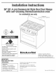


ERemovecardboardorhardboard
fromunderrange.
3 fl'0nt screws
(4 rear screws required
but not shown)
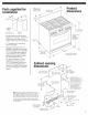
attaching the
backguard
attaching the island
trim
centerh01e
notused
E Attach the backguard or island trim
as required for your installation.
Attachment screws are in the literature
package.
Slide range completely back so
anti-tip bracket is over rear brace of
range.
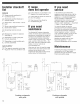
use pipe-joint
regulator flexible
connector
/
union 1/2"t0 3/4" gas
adapter pipe
a 1/2" male pipe thread is neededfor connection
to pressure regulator female pipe threads
E Make gas connection. Assemble
flexible connector from gas supply pipe to
pressure regulator located in the middle
front of the range. Apply pipe-joint
compound made for use with L.R gas to
the smaller thread ends of the flexible
connector adapters. Attach one adapter
to the pressure regulator elbow and the
other adapter to the gas shutoff valve.
Tighten both adapters.
shutoff valve
"open" p
gas supply
line \..,
to range
m Open manual shutoff valve in
gas supply line. Wait a few minutes for
gas to move through the line.
E Leak testing of the appliance
shall be conducted according to the
following instructions:
Use a brush and liquid detergent to test
all gas connections for leaks. Bubbles
around connections will indicate a leak. If
a leak appears, shut off gas valve
controls and adjust connections. Then
check connections again. Clean all
detergent solution from range.
ignitor
electrode
_burnercap
burner
base
m Put a burner cap on each
burner base. Place burner grates over
burner bases and caps.
if your model has only surface burners
(no griNe or griddle), go to "Check the
operation of the surface burners, grille
and griddle" on Page 9.
if your model was shipped with a grille or
griddle, go to "Installing the grille or
griddle" on Page 8 to complete the
installation.
5 m Turn on power supply. "PF"
should appear in the clock display. (Refer
to your Use and Care Guide for
instructions on using the electronic
control.)