
Quick Start Manual

24
3. Test the gas pressure regulator and gas supply line.
The regulator must be checked at a minimum 1" (2.5 cm)
water column above the set pressure. The inlet pressure to
the regulator should be as follows for operation and checking
the regulator setting:
Natural Gas:
Minimum pressure 6" (15.2 cm) WCP
Maximum pressure 14" (35.6 cm) WCP
Gas Supply Pressure Testing
Gas supply pressure for testing regulator must be at least
1" water column pressure above the manifold pressure
shown on the model/serial rating plate.
Line pressure testing above ½ psi gauge (14" WCP)
The range and its individual shutoff valve must be
disconnected from the gas supply piping system during any
pressure testing of that system at test pressures in excess of
½ psi (3.5 kPa).
Line pressure testing at ½ psi gauge (14" WCP) or lower
The range must be isolated from the gas supply piping
system by closing its individual manual shutoff valve during
any pressure testing of the gas supply piping system at test
pressures equal to or less than ½ psi (3.5 kPa).
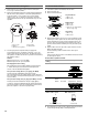
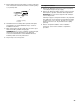
To Convert Surface Burners
1. If the burner grates are installed, remove them.
2. Remove burner cap.
3. Remove the burner base.
4. Apply masking tape to the end of a 7 mm nut driver to help
hold the gas orifice spud in the nut driver while changing it.
Insert nut driver into the gas opening and press down onto
the gas orifice spud and remove by turning the gas orifice
spud counterclockwise and lifting out. Set gas orifice spud
aside.
5. Replace with correct Natural gas orifice spud. See the
“Natural Gas Orifice Spud/Hood Chart.”
Use the following chart to find the exact orifice spud
placement.
Remove choke from medium burner base.
Natural Gas Orifice Spud/Hood Chart
6. Place LP gas orifice spuds in plastic parts bag for future use
and keep with package containing literature.
7. Replace the burner base.
8. Replace burner cap.
9. Repeat steps 2 through 8 for the remaining burners.
To Convert Grill Burner (on some models)
1. Remove grill grate, wave plate, flame spreader and burner
assembly. See “Install Grill Grease Trays” section for removal
instructions. Set parts aside.
2. Use a ½" deep-well socket and remove the LP gas orifice
hood. Replace with correct grill Natural gas orifice hood. See
“Natural Gas Orifice Spud/Hood Chart.”
3. Turn Natural gas orifice hood down tightly onto orifice base.
4. Place LP gas orifice hoods in plastic parts bag for future use
and keep with package containing literature.
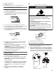
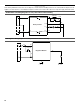
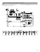
Large Dual Burner
A. Burner cap
B. Burner base
Medium Burner
A. Burner cap
B. Burner base
C. Choke (for use with medium
burner, LP gas only)
Small Burner
A. Burner cap
B. Burner base
A
B
A
B
C
A
B
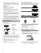
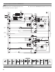
Burner Rating Size Burner Style
5,000 BTU 1.01 mm Small burners
15,000 BTU 1.75 mm Medium burners
20,000 BTU 2.10 mm
0.52 mm
Large burner - main
Large burner - simmer
18,000 BTU 1.93 mm Grill burner
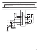
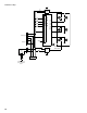
Burner orifice spud Grill orifice hood
A. Size stamp
A. Size stamp
A. Grill orifice hood location
A
A
A