
Operation Manual


10
Installation dimensions
The instructions below, to be carried out in the order in which they are numbered, refer to the figures (with
the same step numbers) given on the last pages of this manual.
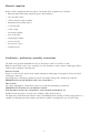
Before starting the installation steps:
- remove the extraction panel “P”
- push the lever (located at the bottom of the panel) to the left
- release the supports panel
- remove the grease filters
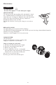
1. Remove the tape fixing the control electronics box to the motor body.
Note: The drawing is only a guide, and the box may be temporarily fixed to other sides of the motor
body.
2. Fully tighten the screws, already partially tightened, that fix the electronics box to the motor body.
3. Adjust the extension of the hood support structure, as the final height of the hood depends on this.
Note: in some cases the support structure is fixed to the motor group with 1 or more screws. Check for
and temporarily remove any screws to enable adjustment of the support structure. Fix the two sections
of the structure using 16 screws (4 each corner).
Note: if required; fit the reinforcement bracket into the truss and place it on the motor unit.
After installing the truss to the ceiling, fix the bracket in its position.
4. Place the ceiling hole diagram directly above the cooktop (the center of the diagram must match the
center of the cooktop and the edges must be parallel to the sides of the cooktop, the side of the diagram
with the wording FRONT (or with the arrows) corresponds to the control panel side).
Prearrange the electrical connection.
5. Drill as shown (6 holes for 6 wall plugs) and insert the 6 plugs in the 6 drilled holes, tighten 4 screws on
the outer holes shown on the drawing, leaving a space of about 1 cm between the screw head and the
ceiling.
6. Fit an exhaust pipe inside the truss and connect it to the collar of the motor compartment (* exhaust pipe
and clamps are not provided).
7. For filter operation (7F), remove the fumes non-return valve “E”, fit the deflector F on the truss and fix
it with 4 screws to the special bracket. Adjust the deflector according to the flue width. Finally, connect
the exhaust pipe to the collar located on the deflector.
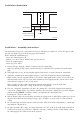
Installation - assembly instructions
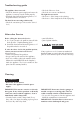
Adjacent wall units Adjacent wall units
central line65 cm (gas or combi cookers)
50 cm (electric cookers)
hob surface
1200 mm min (120 cm wide model)
900 mm min (90 cm wide model)
700 mm min (70 cm wide model)
600 mm min (60 cm wide model)