
Instruction for Use


10
The instructions below, to be carried out in the order in which they are numbered, refer to the figures
(with the same step numbers) given on the last pages of this manual.
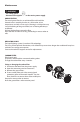
Before starting the installation steps:
- remove the perimeter extraction panel “A”;
- push the lever (located at the bottom of the panel) to the left
- release the panel from the supports
- remove the grease filters
then
- remove the tape fixing the control electronics box “S” to the motor body;
- fully tighten the screws, already partially tightened, that fix the electronics box “S” to the motor body.
Note: the box “S” may be temporarily fixed to the top or sides of the motor body, the image is only for
reference.
1. Using a pencil, draw the center line on the wall up to the ceiling to facilitate installation operations.
2. Place the drilling template against the wall: the vertical center line printed on the template must
match the center line drawn on the wall, and the bottom edge of the drilling template must match
the bottom edge of the hood.
3. Place the lower support bracket on the hole diagram so that it matches the dotted rectangle, mark
the two external holes and drill.
Note: Always perform all the holes indicated on the template: the top 2 holes are for hanging the
hood and the bottom holes (generally 1 central or more side holes) are for fixing it securely to the
wall.
Remove the drilling template, insert the wall plugs and fix the hood support bracket with two 5 x 45
mm screws.
4. Fit the flue support bracket “G” to the wall and against the ceiling, use the support bracket as a hole
diagram (if present, the small slot on the support must match the line drawn on the wall ), mark 2
holes with the pencil then drill the holes (Ø 8 mm) and finally insert 2 plugs.
5. Fix the flue support bracket to the wall with two 5x45 mm screws.
6. Hook the hood to the lower bracket.
7. Adjust the distance between the hood and the wall.
8. Adjust the hood horizontally.
9. Fix the hood securely to the wall (ABSOLUTELY NECESSARY!!).
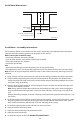
A
djacent wall
units
A
djacent wall
units
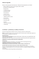
central line65 cm (gas or combi cookers)
50 cm (electric cookers)
hob surface
1200 mm min (120 cm wide model)
900 mm min (90 cm wide model)
700 mm min (70 cm wide model)
6
00 mm min (60 cm wide model)
Installation - assembly instructions
Installation dimensions