
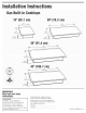
Installation guide


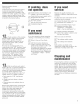
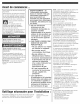

Ebctronicignitionsystemsoperate
withinwidevoitageiimits,butproper
groundandpoiarityarenecessary.In
additionto checkingthattheoutlet
provides120-voitpowerandiscorrecdy
grounded,theoutletmustbecheckedby
aqualifiedeiectricianto seeif itiswired
withcorrectpohrity.Awiringdiagramis
providedintheiiteraturepackage,
iMPORTANT:Thisrangeisequippedwith
aneiectronicignitionsystemthatwHinot
operateif piuggedintoanoutletthatis
notproperlypolarized,
Thisappliance,wheninstalled,mustbe
electricallygroundedinaccordancewith
localcodesor,intheabsenceof local
codes,withthecurrentCSAstandard
C22,1,CanadianElectricalCodePart1,
Recommendedgroundmethod
Foryourpersonalsafety,thiscooktop
mustbegrounded.Thiscooktopis
equippedwitha3opronggroundplug.To
minimizepossibleshockhazard,thecord
mustbepluggedintoamating3-prong
ground-typeoutlet,groundedin
accordancewiththeNationalElectrical
CodeANSI/NFPA70latestedition__or
CanadianElectricalCode(CSA)×,x_--
andlocalcodesandordinances,Ifa
matingoutletisnotavailable,it isthe
personalresponsibilityandobligationof
thecustomerto haveaproperly
polarizedandgrounded,3=prongoutlet
installedbyaqualifiedelectrician,
3-prongpolarized
ground-typeoutlet_
"--a_
3-prong
groundplug
power
supplycord
Now start,,,
With cooktop in kitchen.
Excessive Weight Hazard
Use two or more people to move and
install range.
Failure to do so can result in back or
other injury.
o Remove foam shipping blocks and
tape from cooktop, Untape power supply
cord,
o Remove pressure regulator,
hardware package, burner grates, burner
caps, clamp brackets, and 2ol/2"(6,4 cm)
clamp screws, from shipping package,
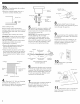
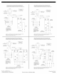
attachment screws
for optional front _...burner box
and back location bottom
attachment
screw
bracket (end _
locations
recommended)
a o if installing before the cooktop
is placed into cutout:
o Place the cooktop upside down on a
protective surface (blanket, pad).
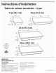
Glass cooktops only:
Remove foam strip from literature
package. Apply foam strip around bottom
of cooktop flush with edge.
o Remove the attachment screws for the
bracket locations selected from the
bottom of the burner box.
o Use bracket mounting holes that will
allow the clamp screws (see Step 4) to
contact the countertop bottom. Attach
brackets as shown then rotate brackets
so that they do not extend beyond edge
of burner box.
oTighten screws just enough to hold
brackets in place when cooktop is
turned over and put into cutout.
oTurn the cooktop right side up and
carefully place into the cutout.
IMPORTANT: Check that the front edge of
the cooktop is parallel to the front edge
of the countertop, Lift entire cooktop up
from cutout when repositioning cooktop
to prevent scratching the countertop,
o Loosen the screws or nuts, rotate the
brackets so that they extend beyond
edge of the burner box,Tighten screws
securely_
Copies of the standards listed may be
obtained from:
_National Fire Protection Association
One Batteryrnarch Park
Quincy, Massachusetts 02269
_*CSA International
8501 East Pleasant \/alley Rd.
Cleveland, OH 44131-5575
"U" shaped spring
clip or small
diameter hole
3o Two clamp brackets are provided
to clamp the cooktop to the countertop,
Install the clamp brackets on each end of
the burner box bottom, Optional: If
cabinet construction does not provide
clearance for installing brackets at burner
box ends, install the brackets on the front
and back of the burner box bottom,
The brackets may be installed before (see
Step 3a) or after (see Step 3b) the
cooktop is placed into the cutout,