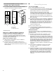
PRO LINE® FRONT-LOADING ELECTRIC DRYER Use & Care Guide For questions about features, operation/performance, parts, accessories or service, call: 1-800-422-1230 or visit our website at... www.kitchenaid.com Table of Contents............................................................................................................
TABLE OF CONTENTS DRYER SAFETY..............................................................................3 INSTALLATION INSTRUCTIONS ..................................................4 Tools and Parts ............................................................................4 Options .........................................................................................4 Location Requirements ................................................................5 Electrical Requirements ...................
DRYER SAFETY Your safety and the safety of others are very important. We have provided many important safety messages in this manual and on your appliance. Always read and obey all safety messages. This is the safety alert symbol. This symbol alerts you to potential hazards that can kill or hurt you and others. All safety messages will follow the safety alert symbol and either the word “DANGER” or “WARNING.
INSTALLATION INSTRUCTIONS ■ Tools and Parts Gather the required tools and parts before starting installation. Read and follow the instructions provided with any tools listed here.
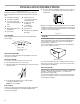
Location Requirements WARNING Dryer Dimensions 57" (144.8 cm) 42"** (106.7 cm) Explosion Hazard Keep flammable materials and vapors, such as gasoline, away from dryer. Place dryer at least 18 inches (46 cm) above the floor for a garage installation. Failure to do so can result in death, explosion, or fire. 33"* (83.8 cm) You will need ■ A location that allows for proper exhaust installation. See “Venting Requirements.” ■ A separate 30 amp circuit.
Recommended installation spacing for cabinet installation, with or without a pedestal ■ For cabinet installation, with a door, minimum ventilation openings in the top of the cabinet are required. 7"* (17.8 cm) 7"* (17.8 cm) Electrical Requirements It is your responsibility ■ To contact a qualified electrical installer. ■ To be sure that the electrical connection is adequate and in conformance with the National Electrical Code, ANSI/NFPA 70-latest edition and all local codes and ordinances.
If using a power supply cord: Use a UL listed power supply cord kit marked for use with clothes dryers. The kit should contain: ■ A UL listed 30-amp power supply cord, rated 120/240 volt minimum. The cord should be type SRD or SRDT and be at least 4 ft (1.22 m) long. The wires that connect to the dryer must end in ring terminals or spade terminals with upturned ends. ■ A UL listed strain relief.
Make Electrical Connection Power Supply Cord Direct Wire WARNING WARNING Fire Hazard Fire Hazard Use a new UL listed 30 amp power supply cord. Use 10 gauge solid copper wire. Use a UL listed strain relief. Use a UL listed strain relief. Disconnect power before making electrical connections. Disconnect power before making electrical connections. Connect neutral wire (white or center wire) to center terminal (silver). Connect neutral wire (white or center wire) to center terminal (silver).
■ Put power supply cord through the strain relief. Be sure that the wire insulation on the power supply cord is inside the strain relief. The strain relief should have a tight fit with the dryer cabinet and be in a horizontal position. Do not further tighten strain relief screws at this point.
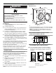
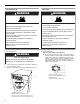
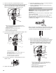
1. Remove center silver-colored terminal block screw. 2. Remove neutral ground wire from external ground conductor screw. Connect neutral ground wire and the neutral wire (white or center wire) of power supply cord under center, silver-colored terminal block screw. Tighten screw. 6. Insert tab of terminal block cover into slot of dryer rear panel. Secure cover with hold-down screw. 7. You have completed your electrical connection. Now go to “Venting Requirements.
3. Connect ground wire (green or bare) of direct wire cable to external ground conductor screw. Tighten screw. 1. Loosen or remove center silver-colored terminal block screw. 2. Connect neutral wire (white or center wire) of power supply cord to the center, silver-colored terminal screw of the terminal block. Tighten screw. C C B D A E B D A F E A. External ground conductor screw B. Ground wire (green or bare) of power supply cord C. Neutral ground wire D.
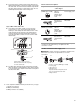
When connecting to the terminal block, place the hooked end of the wire under the screw of the terminal block (hook facing right), squeeze hooked end together and tighten screw, as shown. Optional 3-wire connection Use for direct wire or power supply cord where local codes do not permit connecting cabinet-ground conductor to neutral wire. 1. Remove center silver-colored terminal block screw. 2. Remove neutral ground wire from external ground conductor screw.
Venting Requirements WARNING ■ Remove excess flexible metal vent to avoid sagging and kinking that may result in reduced airflow and poor performance. ■ Do not install flexible metal vent in enclosed walls, ceilings or floors. Elbows 45° elbows provide better airflow than 90° elbows. Fire Hazard Use a heavy metal vent. Do not use a plastic vent. Do not use a metal foil vent. Failure to follow these instructions can result in death or fire.
Plan Vent System Choose your exhaust installation type Determine vent path Recommended exhaust installations ■ This dryer vents from the rear of the dryer. B Select the route that will provide the straightest and most direct path outdoors. ■ Plan the installation to use the fewest number of elbows and turns. ■ When using elbows or making turns, allow as much room as possible. ■ Bend vent gradually to avoid kinking. ■ Use the fewest 90° turns possible.
Install Vent System WARNING Excessive Weight Hazard Use two or more people to move and install dryer. Failure to do so can result in back or other injury. 1. Position the dryer so that the rear of the dryer is within 4 ft (1.2 m) of its final location. 2. Install exhaust hood. Use caulking compound to seal exterior wall opening around exhaust hood. 3. Connect vent to exhaust hood. Vent must fit inside exhaust hood. Secure vent to exhaust hood with 4" (10.2 cm) clamp. 4. Run vent to dryer location.
DRYER USE Starting Your Dryer WARNING WARNING Explosion Hazard Keep flammable materials and vapors, such as gasoline, away from dryer. Do not dry anything that has ever had anything flammable on it (even after washing). Failure to follow these instructions can result in death, explosion, or fire. WARNING: To reduce the risk of fire, electric shock, or injury to persons, read the IMPORTANT SAFETY INSTRUCTIONS before operating this appliance. Follow these basic steps to start your dryer.
■ Press TEMP until the desired temperature illuminates. NOTE: During a Manual Cycle, you can change the settings for Time, Temperature, Extra Care and Cycle End Tone signal. Press PAUSE/CANCEL twice to stop the dryer and clear the settings. Select another cycle or option. 4. (OPTIONAL STEP) If desired, set the Cycle End Tone signal. Select LOUD or SOFT to alert you when a cycle ends. 5. Press and hold START for approximately 3 seconds until dryer starts. Be sure the door is closed.
Check Lint Screen Delicate The Check Lint Screen display reminds you to check the lint screen. CHECK LINT SCREEN is displayed when the machine is turned on. The message turns off when the lint screen is opened and cleaned, Start is pressed, or after 5 minutes have elapsed. Use this cycle to get Low heat for drying synthetic fabrics, washable knit fabrics and no-iron finishes. Extra Delicate Use this cycle to get Extra Low heat to gently dry items such as lingerie, exercise wear or sheer curtains.
Manual Preset Cycle Settings Temperature Manual Cycles Load Type Temp. Default Time (Minutes) TIMED DRY Heavyweight, bulky items, bedspreads, work clothes High 40 TOUCH UP Remove wrinkles Medium 20 RAPID DRY Small loads Medium 27 DRY RACK Dry without tumbling Low* 60 Use these settings to select temperatures for the Manual Cycles. Press the TEMP key until the desired temperature setting glows. Temperature settings cannot be used with the Automatic Cycles.
2. Place drying rack inside dryer drum, positioning the back wire on the ledge of the inner dryer back panel. Push down on front feet of drying rack, at the same time, aligning the locator tabs with the locator indentations in the dryer drum. DRYER CARE Cleaning the Dryer Location Keep dryer area clear and free from items that would obstruct the flow of combustion and ventilation air. A WARNING B C A. Dryer back panel B. Locator tabs C.
To wash 1. Roll lint off the screen with your fingers. 2. Wet both sides of lint screen with hot water. 3. Wet a nylon brush with hot water and liquid detergent. Scrub lint screen with the brush to remove residue buildup. Removing Accumulated Lint From Inside the Dryer Cabinet Lint should be removed every 2 years, or more often, depending on dryer usage. Cleaning should be done by a qualified person. From the Exhaust Vent Lint should be removed every 2 years, or more often, depending on dryer usage.
TROUBLESHOOTING First try the solutions suggested here and possibly avoid the cost of a service call... Dryer Operation Dryer Results Dryer will not run Has a household fuse blown, or has a circuit breaker tripped? There may be 2 household fuses or circuit breakers for the dryer. Check that both fuses are intact and tight, or that both circuit breakers have not tripped. Replace the fuse or reset the circuit breaker. If the problem continues, call an electrician.
Loads are wrinkled WARNING ■ Was the load removed from dryer at the end of the cycle? ■ Was the dryer overloaded? Dry smaller loads that can tumble freely. Odors Explosion Hazard ■ Have you recently been painting, staining or varnishing in the area where your dryer is located? If so, ventilate the area. When the odors or fumes are gone from the area, rewash and dry the clothing. ■ Is the dryer being used for the first time? The new electric heating element may have an odor.
KITCHENAID® PRO LINE™ DRYER WARRANTY FIVE -YEAR PARTS AND LABOR LIMITED WARRANTY For five years from the date of purchase, when this major appliance is operated and maintained according to instructions attached to or furnished with the product, KitchenAid or KitchenAid Canada (hereafter “KitchenAid”) will pay for factory specified replacement parts and repair labor to correct defects in materials or workmanship. Service must be provided by a KitchenAid designated service company.