MICROWAVE HOOD COMBINATION INSTALLATION INSTRUCTIONS This product is suitable for use above electric or gas cooking products up to and including 36" (91.4 cm) wide. See “Installation Requirements” section for further notes. These installation instructions cover different models. The appearance of your particular model may differ slightly from the illustration in these installation instructions. Table of Contents MICROWAVE HOOD COMBINATION SAFETY ....cssssssssssssssesseesseees 1 INSTALLATION REQUIREMENTS ..
INSTALLATION REQUIREMENTS The microwave oven is set for recirculation installation. For external (wall or roof) venting, see “Venting Design Specifications” section. Tacestion LOCATION Check the opening where the microwave oven will be installed. The location must provide: Tools Needed Gather the required tools and parts before starting installation. Read and follow the instructions provided with any tools listed here.
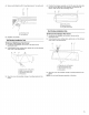
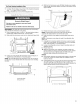
Installation Dimensions NOTE: The grounded 3 prong outlet must be inside the upper cabinet. See “Electrical Requirements” section. wh 12" (30.5 cm) min. 13" (33.0 cm) max. upper cabinet and side cabinet depth Electrical Shock Hazard Plug into a grounded 3 prong outlet. Do not remove ground prong. Do not use an adapter. Do not use an extension cord. Failure to follow these instructions can result in death, fire, or electrical shock. Observe all governing codes and ordinances.
INSTALLATION INSTRUCTIONS 2. With vent deflector oriented as shown (wide side down), slide it back and under the back edge of the vent opening. packaging, or it may be attached to the back of the microwave oven. NOTE: To avoid possible damage to the work surface, cover the work surface. 1. Remove any remaining contents from the microwave oven cavity. 2. Ifthe mounting plate is attached to the back of the microwave oven, remove it and set it aside. 3.
Secure vent deflector with 2 mounting screws (1 on each end). 4. Position the damper assembly so that the long tab slides into the slot on the right side of the damper vent opening, as shown. Then secure with mounting screw. A B meet tg 4. A. Mounting screw B. Damper assembly C. Long tab (inside siot) Roof Venting Installation Only 5. To Remove Roof Damper Vent Cover: 1. Locate the roof damper vent cover on the top of the microwave oven. 2.
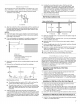
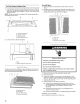
NOTE: If no wall studs exist within the cabinet opening, do not install the microwave oven. 1. Using a stud finder, locate the edges of the wall stud(s) within the opening. See illustrations in “Possible Wall Stud Configurations.” 2. Mark the center of each stud, and draw a plumb line down each stud center. See illustrations in “Possible Wall Stud Configurations.” Possible Wall Stud Configurations These depictions show examples of preferred installation configurations with the mounting plate.
stud, preferably 2, using a minimum 1. 6. Holding the mounting plate in place, find the wall stud centerline(s) drawn in Step 2 of “Locate Wall Stud(s),” and mark at least 1, preferably 2 hole(s) through the mounting plate, closest to the wall stud centerline(s). See figures 1, 2 and/or 3 in “Possible Wall Stud Configurations” in “Locate Wall Stud(s)” section. The blackened holes in the shaded areas are ideal hole locations. 7. Set the mounting plate aside. of 1 lag screw, preferably 2.
g1 6. NOTE: Secure the mounting plate to the drilled into the wall studs and/or drywall using either 1/4-20 x 3" round-head bolts and toggle nuts or 1/4 x 2" lag screws. Refer to illustrations in “Possible Wall Stud Configurations” in “Locate Wall Stud(s)” section. Insert a lag screw into the remaining end hole. If installing on a second wall stud, insert a lag screw into the other hole drilled in Step 2 of “Installation for Wall Stud at One End Hole” in the “Drill Holes in Rear Wall” section. . 8.
4. With front of microwave oven still tilted, thread power supply cord through the power supply cord hole in the bottom of the upper cabinet. 5. Rotate microwave oven up toward upper cabinet. For Roof Venting Installation Only Cut3/4" (19 mm) hole at one corner of the shaded rectangular area “F” on Upper Cabinet Template. 8. Using a keyhole saw, cut out the rectangular area. Le Perce ee 7. ~y Excessive Weight Hazard Use two or more people to move and install microwave oven.
For Roof Venting Installation Only 1. Insert damper assembly through the cabinet cutout so that the long tab of the damper assembly slides into the slot on the left side of the damper vent opening, as shown. Then secure with mounting screw. To Install Filters: 1. Make sure filters are stacked in the filter frame as shown above. 2.
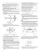
VENTING DESIGN SPECIFICATIONS This section is intended for architectural designer and builder/contractor reference only. NOTES: gm Vent materials needed for installation are not provided with microwave hood combination. We do not recommend using a Rectangular to Round Transition NOTE: The minimum 3" (7.6 cm) clearance must exist between the top of the microwave oven and the rectangular to round transition piece so that the damper can open freely and fully. flexible metal vent.
Recommended Vent Length A 3%" x 10" (8.3 x 25.4 cm) rectangular or 6" (15.2 cm) round vent should be used. 6" (15.2 cm) vent system = 73 ft (22.2 m) total The total length of the vent system including straight vent, elbows), transitions and wall or roof caps must not exceed the equivalent of 140 ft (42.7 m) for either type of vent. See “Recommended Standard Fittings” section for equivalent lengths. A B : 6 ft (1.8m) ». For best performance, use no more than three 90° elbows.