
Installation Instruction


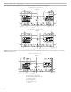
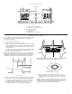


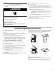

Table Of Contents

11
Complete Installation
1. Install filters. Refer to the User Instructions for filter
placement.
2. Plug microwave oven into grounded 3 prong outlet.
3. Reconnect power.
4. Check the operation of microwave oven by placing 1 cup
(250 ml) of water on the turntable and programming a cook
time of 1 minute at 100% power. Test vent fan and exhaust
by operating the vent fan.
5. If the microwave oven does not operate:
■ Check that a household fuse has not blown, or that a
circuit breaker has not tripped. Replace the fuse or reset
the circuit breaker. If the problem continues, call an
electrician.
■ Check that the power supply cord is plugged into a
grounded 3 prong outlet.
■ See the User Instructions for troubleshooting information.
Installation is now complete.
Save Installation Instructions for future use.
VENTING DESIGN SPECIFICATIONS
This section is intended for architectural designer and builder/
contractor reference only.
NOTES:
■ Vent materials needed for installation are not provided with
microwave hood combination.
■ We do not recommend using a flexible metal vent.
■ To avoid possible product damage, be sure to vent air
outside, unless using recirculation installation. Do not vent
exhaust air into concealed spaces, such as spaces within
walls or ceilings, attics, crawl spaces, or garages.
For optimal venting installation, we recommend:
■ Using roof or wall caps that have back draft dampers
■ Using a rigid metal vent
■ Using the most direct route by minimizing the length of the
vent and number of elbows to provide efficient performance
■ Using uniformly sized vents
■ Using duct tape to seal all joints in the vent system
■ Using caulking compound to seal exterior wall or roof
opening around cap
■ Not installing 2 elbows together for optimal hood
performance
If venting through the wall, be sure that there is proper clearance
within the wall for the damper to open fully.
If venting through the roof, and rectangular-to-round transition is
used, be sure there are at least 3” (7.6 cm) of clearance between
the top of the microwave oven and the transition piece. See
“Rectangular-to-Round Transition” illustration.
Rectangular-to-Round Transition
NOTE: The minimum 3” (7.6 cm) clearance must exist between
the top of the microwave oven and the rectangular to round
transition piece so that the damper can open freely and fully.
Electrical Shock Hazard
Plug into a grounded 3 prong outlet.
Do not remove ground prong.
Do not use an adapter.
Do not use an extension cord.
Failure to follow these instructions can result in death,
fire, or electrical shock.
WARNING
Roof venting Roof cap
Wall venting Wall cap