
Installation Instruction
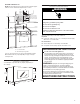
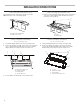
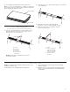
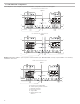
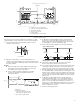
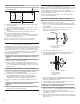
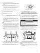
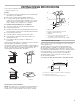
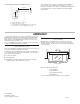
Table Of Contents

11
VENTING DESIGN SPECIFICATIONS
This section is intended for architectural designer and builder/
contractor reference only.
NOTES:
■ Vent materials needed for installation are not provided with
microwave hood combination.
■ We do not recommend using a flexible metal vent.
■ To avoid possible product damage, be sure to vent air
outside, unless using recirculation installation. Do not vent
exhaust air into concealed spaces, such as spaces within
walls or ceilings, attics, crawl spaces, or garages.
For optimal venting installation, we recommend:
■ Using roof or wall caps that have back draft dampers
■ Using a rigid metal vent
■ Using the most direct route by minimizing the length of the
vent and number of elbows to provide efficient performance
■ Using uniformly sized vents
■ Using duct tape to seal all joints in the vent system
■ Using caulking compound to seal exterior wall or roof
opening around cap
■ Not installing 2 elbows together for optimal hood
performance
If venting through the wall, be sure that there is proper clearance
within the wall for the damper to open fully.
If venting through the roof, and rectangular-to-round transition is
used, be sure there are at least 3" (7.6 cm) of clearance between
the top of the microwave oven and the transition piece. See
“Rectangular-to-Round Transition” illustration.
Rectangular-to-Round Transition
NOTE: The minimum 3" (7.6 cm) clearance must exist between
the top of the microwave oven and the rectangular to round
transition piece so that the damper can open freely and fully.
Recommended Vent Length
A 3¹⁄
4
" x 10" (8.3 x 25.4 cm) rectangular or 6” (15.2 cm) round
vent should be used.
The total length of the vent system including straight vent,
elbow(s), transitions, and wall or roof caps must not exceed
the equivalent of 140 ft (42.7 m) for either type of vent. See the
“Recommended Standard Fittings” section for equivalent lengths.
For best performance, use no more than three 90° elbows.
To calculate the length of the system you need, add the
equivalent lengths of each vent piece used in the system.
See the following examples.
3¹⁄
4
" x 10" (8.3 x 25.4 cm) vent system = 73 ft (22.2 m) total.
Roof venting Roof cap
Wall venting Wall cap
A
B
C
E
F
D
3" (7.6 cm)
A. Roof cap
B. 6" (15.2 cm) min. diameter round vent
C. Elbow (for wall venting only)
D. Wall cap
E. 3¹⁄
4
" x 10" to 6" (8.3 x 25.4 cm to 15.2 cm)
rectangular to round transition piece
F. Vent extension piece, at least 3" (7.6 cm) high
A B
C
6 ft (1.8 m)
2 ft
(0.6 m)
A. One 3¹⁄
4
" x 10” (8.3 x 25.4 cm) 90° elbow = 25 ft (7.6 m)
B. 1 wall cap = 40 ft (12.2 m)
C. 2 ft (0.6 m) + 6 ft (1.8 m) straight = 8 ft (2.4 m)