
Owner's Manual


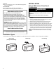
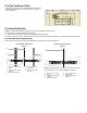

Table Of Contents
- MICROWAVE OVEN SAFETY
- Microwave Oven Safety
- MICROWAVE OVEN MAINTENANCE AND CARE
- General Cleaning
- INSTALLATION INSTRUCTIONS
- REQUIREMENTS
- Tools and Parts
- Location Requirements
- Product Dimensions
- Installation Dimensions
- Electrical Requirements
- INSTALLATION
- Prepare Microwave Oven Hood Combination
- Installation Types
- Find the Cardboard Plate
- Find the Wall Stud(s)
- Find the Flush Point
- Mark Upper Cabinet
- Mark Rear Wall
- Drill holes in Upper Cabinet
- Drill holes in Rear Wall
- Attach Mounting Plate to Wall
- Rotate Blower Motor
- Install Damper Assembly
- Install the Microwave Oven
- Complete Installation
- VENTING DESIGN SPECIFICATIONS
- Venting Design Specifications
- SEGURIDAD DEL HORNO MICROONDAS
- Seguridad del horno de microondas
- MANTENIMIENTO Y CUIDADO DEL HORNO MICROONDAS
- Limpieza general
- INSTRUCCIONES DE INSTALACIÓN
- REQUISITOS
- Herramientas y piezas
- Requisitos de Ubicación
- Dimensiones del producto
- Dimensiones de instalación
- Requisitos eléctricos
- INSTALACIÓN
- Preparar la combinación de horno de microondas y campana
- Tipos de instalación
- Encontrar plantilla de cartón
- Encontrar las vigas de pared
- Encontrar el Punto al Ras
- Marcar gabinete superior
- Marque la pared posterior
- Taladrar los orificios en el gabinete superior
- Taladre orificios en la pared posterior
- Fije la placa de montaje a la pared
- Gire el Motor del Soplador
- Instale el Conjunto de la Compuerta
- Instalación del horno de microondas
- Complete la instalación
- ESPECIFICACIONES PARA EL DISEÑO DE LA VENTILACIÓN
- Especificaciones para el Diseño de la Ventilación

9
Find the Cardboard Plate
The cardboard plate is used as wall template and upper-cabinet
template. It is located on the outer foam in the carton. Find it
before installation.
Find the Wall Stud(s)
NOTE: If no wall studs exist within the cabinet opening, do not install the microwave oven.
See illustrations in “Possible Wall Stud Configurations.”
1. Using a stud finder, locate the edges of the wall stud(s) within the opening.
2. Mark the center of each stud, and draw a plumb line down each stud center. See illustrations in “Possible Wall Stud Configurations.”
Possible Wall Stud Configurations
These depictions show examples of preferred installation configurations with the mounting plate.
No Wall Studs at End Holes
Figure 1
A
A
B
C
C
D
E
E
F
A. End holes (on mounting
plate)
B. Cabinet opening vertical
centerline
C. Wall stud centerlines
D. Holes for lag screws
E. Support tabs
F. Mounting plate center
markers
No Wall Studs at End Holes
Figure 2
A
A
B
C
D
E
E
F
NOTE: If wall stud is within 6" (15.2 cm) of the vertical centerline,
only recirculation or roof venting installation can be done.
A. End holes (on mounting
plate)
B. Cabinet opening vertical
centerline
C. Wall stud centerlines
D. Holes for lag screws
E. Support tabs
F. Mounting plate center
markers