
Bump Out Kit Installation Instructions


3
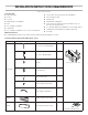
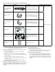
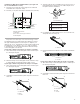
Parts Needed (Provided in the Bump Out Mounting Kit)
Part Drawing Description Quantity Where can nd?
13" ~ 14" L Bracket
Bump Out Mounting
Plate Folded
Folded Mounting plate with L
bracket unfold before installation
1
Bump out mounting
kit
14" ~ 15" M and N
Bracket
M side for 14" (35.6 cm) ~ 14
1
⁄
2
"
(36.8 cm) depth N side for 14
1
⁄
2
"
(36.8 cm) ~ 15" (38.1 cm) depth
2
15" ~ 16" P and R
Bracket
P side for 15" (38.1 cm) ~ 15
1
⁄
2
"
(39.4 cm) depth R side for 15
1
⁄
2
"
(39.4 cm) ~ 16" (40.6 cm) depth
2
Wall Template Wall Template 1
Upper Cabinet Template
Upper cabinet template for 13"
(33 cm) to 16" (40.6 cm) depth
cabinet
1
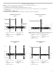
Bump Out Kit Installation
Instruction
Installation Instruction 1
Keep the mounting plate and cardboard template provided with the microwave oven for future use if necessary.
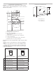
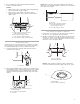
Location Requirements
Check the opening where the microwave oven will be installed.
The location must provide:
■ Minimum installation dimensions. See the “Installation
Dimensions” illustration.
■ Minimum one 2" x 4" (51 x 102 mm) wood wall stud and
minimum 3/8" (10 mm) thickness drywall or plaster/lath within
cabinet opening.
■ Support for weight of 150 lbs (68 kg) which includes
microwave oven and items placed inside the microwave oven
and upper cabinet.
■ Grounded electrical outlet inside upper cabinet. See the
“Electrical Requirements” section.
NOTE: Some cabinet and building materials are not designed to
withstand the heat produced by the microwave oven for cooking.
Check with your builder or cabinet supplier to make sure that
the materials used will not discolor, delaminate, or sustain other
damages.
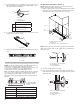
Special Requirements
For Wall Venting Installation Only:
■ Cutout must be free of any obstructions so that the vent t
properly and the damper blade opens freely and fully.
For Roof Venting Installation Only:
■ If you are using a rectangular-to-round transition piece, the
3" (76 mm) clearance needs to exist above the microwave
oven so that the damper blade can open freely and fully. See
“Rectangular to Round Transition” illustration in the “Venting
Design Specications” section on the Owner Manual on the
product.