
Owner's Manual


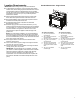


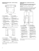
Table Of Contents
- BUILT-IN OVEN SAFETY
- Built-In Oven Safety
- OVEN MAINTENANCE AND CARE
- General Cleaning
- Self-Cleaning Cycle
- Steam Clean (on some models)
- INSTALLATION INSTRUCTIONS
- REQUIREMENTS
- Tools and Parts
- Location Requirements
- Electrical Requirements
- INSTALLATIONS
- Prepare Built-In Oven
- Remove Oven Door(s)
- Positioning Oven Feet for Multiple Cabinet Cutout Heights
- Make Electrical Connection
- Install Oven
- Install Deflector Kit (on some models)
- Replace Oven Door(s)
- Complete Installation
- SÉCURITÉ DU FOUR ENCASTRÉ
- Sécurité du four encastré
- ENTRETIEN ET RÉPARATION DU FOUR
- Nettoyage général
- Programme d’autonettoyage
- Steam Clean (nettoyage à la vapeur) (sur certains modèles)
- INSTRUCTIONS D’INSTALLATION
- SPÉCIFICATIONS
- Outils et pièces
- Exigences d’emplacement
- Spécifications électriques
- INSTALLATION
- Préparer le four encastré
- Enlever la/les porte(s) du four
- Positionner les pieds du four pour des ouvertures de découpe dans l’armoire
- Raccordement électrique
- Installation du four
- Installation de l’ensemble de déflecteurs (sur certains modèles)
- Réinstallation de la/des porte(s) du four
- Achever l’installation
- SEGURIDAD DEL HORNO INTEGRADO
- Seguridad del horno integrado
- MANTENIMIENTO Y CUIDADO DEL HORNO
- Limpieza general
- Ciclo de autolimpieza
- Steam Clean (Limpieza con vapor) (en algunos modelos)
- INSTRUCCIONES DE INSTALACIÓN
- REQUISITOS
- Herramientas y piezas
- Requisitos de ubicación
- Requisitos eléctricos
- INSTALACIONES
- Preparación del horno empotrado
- Retire las puertas del horno
- Ubicación de las patas del horno para múltiples alturas de corte del armario
- Hacer la conexión eléctrica
- Para instalar el horno
- Instale el kit de deflector (en algunos modelos)
- Vuelva a colocar las puertas del horno
- Finalización de la instalación

7
Location Requirements
IMPORTANT: Observe all governing codes and ordinances.
� To eliminate the risk of burns or fire by reaching over heated
surface units, cabinet storage space located above the surface
units should be avoided. If cabinet storage is to be provided,
the risk can be reduced by installing a range hood that projects
horizontally a minimum of 5" (12.7 cm) inches beyond the
bottom of the cabinets.
� Cabinet opening dimensions that are shown must be used.
Given dimensions provide minimum clearance with oven.
� Recessed installation area must provide complete enclosure
around the recessed portion of the oven.
� Grounded electrical supply is required. See “Electrical
Requirements” section.
� Electrical supply junction box should be located 3" (7.6 cm)
maximum below the support surface when the oven is installed
in a wall cabinet. A 1" (2.5 cm) minimum diameter hole should
have been drilled in the right rear or left rear corner of the
support surface to pass the appliance cable through to the
junction box.
NOTE: For undercounter installation, it is recommended that
the junction box be located in the adjacent right or left cabinet.
If you are installing the junction box on rear wall behind oven, it
is recommended that the junction box be recessed and located
in the upper center of the cabinet.
� Oven support surface must be solid, level and flush with
bottom of cabinet cutout.
� Floor must be able to support a single oven weight of 200 lbs
(91 kg) for 30" (76.2 cm) models.
� Floor must be able to support a double oven weight of 330 lbs
(150 kg) for 30" (76.2 cm) models.
IMPORTANT: To avoid damage to your cabinets, check with
your builder or cabinet supplier to make sure that the materials
used will not discolor, delaminate or sustain other damage.
This oven has been designed in accordance with the
requirements of UL and CSA International and complies with
the maximum allowable wood cabinet temperatures of 194°F
(90°C).
Product Dimensions - Single Ovens
B
D
E
A
C
G
F
27" (68.6 cm) models
A. 29" (73.6 cm) maximum
overall height
B. 25
7
/
16
" (64.6 cm) maximum
recessed width
C. 26" (65.9 cm) recessed height
D. 23
1
/
4
" (59.1 cm) maximum
recessed depth
E. 26" (65.9 cm) overall width
F. 12" (30.5 cm) from back of
control panel to start of strain
relief
G. 48" (121.9 cm) flexible
conduit length
30" (76.2 cm) models
A. 29" (73.6 cm) maximum
overall height
B. 28
7
/
16
" (72.2 cm) maximum
recessed width
C. 26" (65.9 cm) recessed height
D. 23
1
/
4
" (59.1 cm) maximum
recessed depth
E. 29
3
/
4
" (75.6 cm) overall width
F. 12" (30.5 cm) from back of
control panel to start of strain
relief
G. 48" (121.9 cm) flexible
conduit length