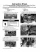
Instruction Sheet for SxS 36” Bottom Mounts and 42” French Door Bottom Mount Models High Voltage Assembly Installation NOTE: The High Voltage (HV) Assembly you receive may not look the same as the control shown in the Instructions or the control you are replacing. Do not remove any components off the new assembly to replace components on the old assembly. This must be installed as a complete assembly. Kit Contains: 1 High Voltage (HV) Assembly 1 Foil Tape 1 instruction Sheet 1. Remove the front grill 2.
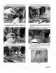
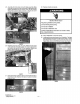
9. Disconnect freezer compartment connections by disconnect. Ing the three connectors in the left grommet. Ses Figure 7. Firelight 10. Disconnect refrigerator compartment connections by disconnecting the three connectors in the right grommet, See Figure 8. HOUSED 11. Remove the grounding wire connections fo the unit high vantage (HV) box assembly. Set screws aside. See Figure 9. FIGURE 12. Remove prows cons strain relief. Set screws aside and remove the HY box assembly from the unit. See Figure 10. FORE 13.
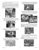
15. Remove the two screws holding the switch plate assembly to the original HV box assembly. NOTE: Following the removal of the screws, the switch plate assembly will still be held io the original HY box assembly by the two wires from the master power switch (and, depending on mode, pessimal the end of line testing connector). See Figure 73. IMPORTANT: Not all models that use this kit will have a testing won nectar, or hole for it in the switch plate assembly.
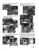
. Connect all connectors, starting with the five connectors near the compressor side disconnected in pies 6. See Figure 21. 23. Connect all the HV box assembly contentions from step 7 through step 10. See Figure 22. 24. Reconnect the grounding wire connections using the screws. from step 11. Re-install screw to power cord strain relief removed in step 12. See Figure 23. NOTE: This is how the HV box assembly will look Like once all the connections are made. See Figure 24.
. Assemble the front panel and switch plate assembly. Make sure that the switch and test connectors {if applicable) align before assembling the front panel. There are two screws which need fo be mounted as shown in Figure 26. Screw quantity and locations will depend on medal, BEEFBURGER 26. Reattach dog house ({op unit cover). Make sure the screw on the fight side of dog house (top unit cover} is aligned with the hole on the side of the HV box assembly. Attach front panel to dog house (top unit cover).