
Installation Instruction


5
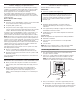
■ Slip compression sleeve and compression nut on copper
tubing as shown. Insert end of tubing into outlet end
squarely as far as it will go. Screw compression nut onto
outlet end with adjustable wrench. Do not overtighten.
4. Place the free end of the tubing into a container or sink, and
turn on main water supply and ush out tubing until water is
clear. Turn off shutoff valve on the water pipe.
IMPORTANT: Always drain the water line before making
the nal connection to the inlet of the water valve to avoid
possible water valve malfunction.
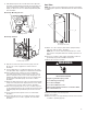
5. Bend the copper tubing to meet the water line inlet which is
located on the back of the ice maker cabinet as shown. Leave
a coil of copper tubing to allow the ice maker to be pulled out
of the cabinet or away from the wall for service.
Rear View
6. Remove and discard the short, black plastic tube from the
end of the water line inlet.
7. Thread the nut onto the end of the tubing. Tighten the nut by
hand. Then tighten it with a wrench two more turns. Do not
overtighten.
NOTE: To avoid rattling, be sure the copper tubing does not
touch the cabinet’s side wall or other parts inside the cabinet.
8. Install the water supply tube clamp around the water supply
line to reduce strain on the coupling.
9. Turn shutoff valve ON.
10. Check for leaks. Tighten any connections (including
connections at the valve) or nuts that leak.
Drain Pump Installation
(on some models)
NOTES:
■ Connect drain pump to your drain in accordance with all state
and local codes and ordinances.
■ It may be desirable to insulate drain tube thoroughly up
to drain inlet to minimize condensation on the drain tube.
Insulated tube kit Part Number W10365792 is available for
purchase.
■ Drain pump is designed to pump water to a maximum height
of 10 ft (3 m). Use only Whirlpool approved drain pump kit
Part Number 1901A.
■ Do not connect the outlet end of the drain tube to a closed
pipe system to keep drain water from backing up into the ice
maker.
Kit Contains:
■ Drain pump kit Part Number 1901A
■ 5/8" I.D. x 5
1
/
8
" drain tube (ice maker bin to drain pump
reservoir inlet)
■ 1/2" I.D. x 10 ft (3 m) drain tube hose (drain pump discharge
to household drain)
■ 5/16" I.D. x 32" (81 cm) vent tube (drain pump reservoir vent
to ice maker cabinet back)
■ Cable tie (secures vent tube to black suction tube) (1)
■ #8-32 x 3/8" pump mounting screws (secures drain pump to
baseplate and clamps to back of ice maker) (5)
■ 5/8" small adjustable hose clamp (secures vent to drain
pump)
■ 7/8" large adjustable hose clamp, (secures drain tube to ice
maker bin and drain pump reservoir inlet) (3)
■ Rear panel (2)
■ Instruction sheet
If Ice Maker Is Currently Installed
NOTE: If ice maker is not installed, please proceed to “Drain
Pump Installation” section.
1. Push the selector switch to the OFF position.
B
C
A
A. Compression sleeve
B. Compression nut
C. Copper tubing
A
C
B
A. Copper tubing
B. Water supply tube clamp
C. Inlet water tube clamp and
supply line connector
DAB C
WARNING
Electrical Shock Hazard
Disconnect power before servicing.
Replace all parts and panels before operating.
Failure to do so can result in death or electrical shock.
A. Line to ice maker
B. Nut (purchased)
C. Ferrule (purchased)
D. Supplied line from ice maker