
Owner's Manual
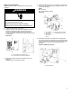
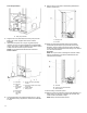
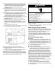
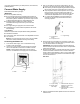
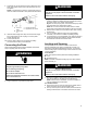
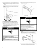
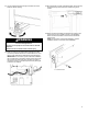
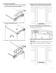
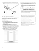
Table Of Contents
- ICE MAKER SAFETY
- Ice Maker Safety
- IMPORTANT CONSUMER INFORMATION
- Important Consumer Information
- ICE MAKER MAINTENANCE AND CARE
- How Ice Maker Works
- Normal Sounds
- Water Filtration System
- Interior Cleaning
- Exterior Cleaning
- Vac Extn Time Without Use
- INSTALLATION INSTRUCTIONS
- Unpack Ice Maker
- Location Requirements
- Electrical Requirements
- Drain Connection Requirements
- Drain Pump Installation (on some models)
- Water Supply Requirements
- Connect Water Supply
- Connecting the Drain
- Leveling and Securing
- Custom Wood Panel
- Auxiliary Grille Installation
- SECURITE DE LA MACHINE A GLACONS
- Sécurité de la machine à glaçons
- RENSEIGNEMENTS IMPORTANTS POUR LE CONSOMMATEUR
- Renseignements importants pour le consommateur
- ENTRETIEN ET REPARATION DE LA MACHINE A GLACONS
- Comment utiliser la machine à glaçons
- Sons normaux
- Système de filtration d’eau
- Nettoyage de l’intérieur
- Nettoyage des surfaces externes
- Vacances ou longue période d’inutilisation
- INSTRUCTIONS D'INSTALLATION
- Déballage de la machine à glaçons
- Exigences d’emplacement
- Electrical Requirements
- Exigences concernant le raccordement au drain
- Installation de la pompe de vidange (sur certains modèles)
- Spécifications de l’alimentation en eau
- Raccordement à la canalisation d’eau
- Raccordement de la vidange
- Leveling and Securing
- Panneau de bois personnalisé
- Installation de la grille auxiliaire

12
Drain Pump Installed
A. Drain pump installed
6. Align the two screw holes at the rear of the pump. Use two
#832 x 3/8ʺ screws, supplied. See “Parts Locations”
illustration.
7. Install vent tube (5/16" I.D. x 32" [81 cm]) to drain pump
reservoir vent. Use one of the supplied 5/8" small adjustable
clamps. See “Parts Locations” illustration. Use plastic retainer
to keep vent hose secure to top of inner deck.
NOTE: Do not install household drain tube at this time.
Parts Locations
A. Vent tube
B. 5/8" hose
clamp
C. Drain pump
discharge
tube
D. Drain pump
E. Ice maker
unit power
cord
F. #8-32 x 3/8" pump mounting
screws
G. Drain pump power cord, clamp,
and screw
H. Plastic retainer
I. Wiring cover
8. Connect drain tube to ice maker bin outlet (5/8ʺ I.D.), using
7/8ʺ adjustable clamp, supplied. See “Drain Tube” illustration
in step 4.
9. Remove wiring cover. Refer to the following illustration for
location of the screws.
A. Wiring cover
B. Screws
10. Route vent tube through plastic retainer that is located
underneath top deck in open pump area as shown in the
illustration. Using a cable tie, tie the vent tube to the black
suction tube which is located behind the wiring cover. Refer to
the “Vent Tube” illustration.
Vent Tube
NOTE: Do not pinch, kink, or damage the vent tube. Check
that it is not damaged or pinched or kinked between the
cabinet and the ice maker.
A. Vent tube
B. Clamps and screws/Cable ties
C. Plastic retainer
11. Secure wiring cover back in place.
12. Remove power cord clamp and ground screw attached to ice
maker power cord, which is mounted to the unit base. See
“Parts Locations” illustration in step 7.
NOTE: Clamp and screw will be reused.