
Installation Instructions
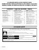


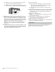
Table Of Contents
- Ice maker SAFETY
- INSTALLATION INSTRUCTIONS
- Unpack the Ice Maker
- Vacation or Extended Time Without Use
- Location Requirements
- Electrical Requirements
- Water Supply Requirements
- Drain Connection Requirements
- Door Reversal
- Drain Pump Installation (on some models)
- Connect Water Supply
- Leveling and Securing
- Custom Wood Panel
- Connecting the Drain
- Auxiliary Grill Installation
- Deep Clean
- SÉCURITÉ DE LA MACHINE À GLAÇONS
- INSTRUCTIONS D’INSTALLATION
- Déballage de la machine à glaçons
- Vacances ou longue période d’inutilisation
- Exigences d’emplacement
- Spécifications électriques
- Spécifications de l’alimentation en eau
- Exigences concernant le raccordement au drain
- Inversion de la porte
- Installation de la pompe de vidange (sur certains modèles)
- Raccordement à la canalisation d’eau
- Mettre de niveau et sécuriser
- Panneau de bois personnalisé
- Raccordement de la vidange
- Installation de la grille auxiliaire
- Nettoyage en profondeur
- SEGURIDAD DE LA FÁBRICA DE HIELO
- INSTRUCCIONES DE INSTALACIÓN
- Cómo desempacar la máquina de hielo
- Vacaciones o tiempo prolongado sin uso
- Requisitos de ubicación
- Requisitos eléctricos
- Requisitos del suministro de agua
- Requisitos para la conexión del desagüe
- Cambio del sentido de apertura de la puerta
- Instalación de la bomba de desagüe (en algunos modelos)
- Conexión del suministro de agua
- Nivelado y asegurado
- Panel de madera personalizado
- Conexión del desagüe
- Instalación de la rejilla auxiliar
- Limpieza intensa

2 3
INSTALLATION INSTRUCTIONS
Unpack the Ice Maker
Removing Packaging Materials
Remove tape and glue from your ice maker before using.
■ To remove any remaining tape or glue from the exterior of the
ice maker, rub the area briskly with your thumb. Tape or glue
residue can also be easily removed by rubbing a small
amount of liquid dish soap over the adhesive with your
ngers. Wipe with warm water and dry.
■ Do not use sharp instruments, rubbing alcohol, ammable
uids, or abrasive cleaners to remove tape or glue. Do not
use chlorine bleach on the stainless steel surfaces of the ice
maker. These products can damage the surface of your ice
maker.
Cleaning Before Use
After you remove all of the packaging materials, clean the inside
of your ice maker before using it. See the cleaning instructions in
the “Ice Maker Care” section of Use and Care Guide.
Vacation or Extended Time Without Use
■ When you will not be using the ice maker for an extended
period of time, turn off the water and power supply to the ice
maker.
■ Check that the water supply lines are insulated against
freezing conditions. Ice formations in the supply lines can
increase water pressure and cause damage to your ice
maker or home. Damage from freezing is not covered by the
warranty.
Location Requirements
■ Installation must comply with all governing codes and
ordinances.
■ To ensure proper ventilation for your ice maker, the front
side must be completely unobstructed. The ice maker may
be closed-in on the top and three sides, but the installation
should allow the ice maker to be pulled forward for servicing if
necessary.
■ The auxiliary grill kit provided (only on custom panel models)
can be used to align the toe grill with the rest of the cabinets
while not obstructing ventilation of the ice maker.
■ Installation of the ice maker requires a cold water supply inlet
of 1/4" (6.35 mm) OD soft copper tubing with a shutoff valve
or a Whirlpool supply line Part Number 8212547RB, and a
Whirlpool approved drain pump, Part Number 1901A, only to
carry the water to an existing drain.
■ Choose a well-ventilated area with temperatures above 55°F
(13°C) and below 110°F (43°C). Best results are obtained
between 70°F and 90°F (21ºC and 32°C).
■ The ice maker must be installed in an area sheltered from the
elements, such as wind, rain, water spray, or drip.
■ When installing the ice maker under a counter, follow the
recommended opening dimensions shown. Place electrical
and plumbing xtures in the recommended location as shown.
NOTES:
■ Check that the power supply cord is not damaged or
pinched or kinked between the ice maker and the cabinet.
■ Check that the water supply line is not damaged or
pinched or kinked between the ice maker and the cabinet.
■ Check that the drain line (on some models) is not
damaged or pinched or kinked between the ice maker and
the cabinet.
■ Choose a location where the oor is even. It is important for
the ice maker to be level in order to work properly. If needed,
you can adjust the height of the ice maker by changing the
height of the leveling legs. See “Leveling and Securing.”
IMPORTANT SAFETY INSTRUCTIONS
WARNING:
To reduce the risk of fire, electric shock, or injury to persons when using your appliance, follow basic precautions,
including the following:
Children should be supervised to ensure that they do not
play with the appliance.
This appliance is not intended for use by persons (including
children) with reduced physical, sensory, or mental
capabilities, or lack of experience and knowledge, unless
they have been given supervision or instruction concerning
use of the appliance by a person responsible for their
safety.
Do not use an extension cord.
If power supply cord is damaged, it must be replaced by the
manufacturer, its service agent, or a similarly qualified
person in order to avoid a hazard.
Connect to potable water supply only.
This appliance is intended to be used in household and
similar applications such as: staff kitchen areas in shops,
offices, and other working environments; farm houses and
by clients in hotels, motels, and other residential-type
environments; bed and breakfast-type environments; and
catering and similar non-retail applications.
Do not store explosive substances such as aerosol cans
with a flammable propellant in this appliance.
Do not use replacement parts that have not been
recommended by the manufacturer (e.g., parts made at
home using a 3D printer).
SAVE THESE INSTRUCTIONS
WARNING
Excessive Weight Hazard
Use two or more people to move and install ice maker.
Failure to do so can result in back or other injury.
Model Identication:
Standard Model Utilities
Custom Panel Model Utilities
Utility Slot/Cutout Location Zone
Dimension
A 9" (22.9 cm)
B 8" (20.3 cm)
C 7" (17.8 cm)
Diameter of the hole D 2" (5 cm)
■ Custom Panel ice maker models have been designed for ush
install in instances where the power supply, water supply, and
drain are located in adjacent cabinetry.
■ For installation of product with utilities behind the ice maker,
ush install may not be achieved.
■ Refer “Custom Panel Model Utilities” illustration and table
below it for utility slot/hole cutout location.
Electrical Requirements
Before you move your ice maker into its nal location, it is
important to make sure you have the proper electrical connection:
A 115 V, 60 Hz, AC only, 15 A or 20 A electrical supply, properly
grounded in accordance with the National Electrical Code and
local codes and ordinances, is required.
It is recommended that a separate circuit, serving only your ice
maker, be provided. Use a receptacle which cannot be turned off
by a switch or pull chain.
IMPORTANT: If this product is connected to a GFCI (Ground
Fault Circuit Interrupter) equipped outlet, nuisance tripping of the
power supply may occur, resulting in loss of cooling. Ice quality
may be affected. If nuisance tripping has occurred, and if the
condition of the ice appears poor, dispose of it.
Recommended Grounding Method
The ice maker must be grounded. The ice maker is equipped with
a power supply cord having a 3 prong grounding plug. The cord
must be plugged into a mating, 3 prong, grounding-type wall
receptacle, grounded in accordance with the National Electrical
Code and local codes and ordinances. If a mating wall receptacle
is not available, it is the personal responsibility of the customer to
have a properly grounded, 3 prong wall receptacle installed by a
qualied electrician.
Standard model
B
A
A. Recommended location for electrical and plumbing xtures
B. Floor level
C
D
A
B
Electrical Shock Hazard
Plug into a grounded 3 prong outlet.
Do not remove ground prong.
Do not use an adapter.
Do not use an extension cord.
Failure to follow these instructions can result in death,
fire, or electrical shock.
WARNING
34"
(86.4 cm)
Min.
34¹⁄
2
"
(87.6 cm)
Max.
24"
(60.96 cm)
28¹⁄
2
"
(72.4 cm)
3¹⁄
2
"
(8.9 cm)
11¹⁄
2
"
(29.2 cm)
9"
(22.9 cm)
Custom panel model
7½"
(19.05 cm)
7½"
(19.05 cm)
Required zone
for utility hole/slot
cutout location