
Installation Instructions
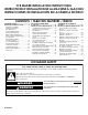


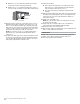
Table Of Contents
- Ice maker SAFETY
- INSTALLATION INSTRUCTIONS
- Unpack the Ice Maker
- Vacation or Extended Time Without Use
- Location Requirements
- Electrical Requirements
- Water Supply Requirements
- Drain Connection Requirements
- Door Reversal
- Drain Pump Installation (on some models)
- Connect Water Supply
- Leveling and Securing
- Custom Wood Panel
- Connecting the Drain
- Auxiliary Grill Installation
- Deep Clean
- SÉCURITÉ DE LA MACHINE À GLAÇONS
- INSTRUCTIONS D’INSTALLATION
- Déballage de la machine à glaçons
- Vacances ou longue période d’inutilisation
- Exigences d’emplacement
- Spécifications électriques
- Spécifications de l’alimentation en eau
- Exigences concernant le raccordement au drain
- Inversion de la porte
- Installation de la pompe de vidange (sur certains modèles)
- Raccordement à la canalisation d’eau
- Mettre de niveau et sécuriser
- Panneau de bois personnalisé
- Raccordement de la vidange
- Installation de la grille auxiliaire
- Nettoyage en profondeur
- SEGURIDAD DE LA FÁBRICA DE HIELO
- INSTRUCCIONES DE INSTALACIÓN
- Cómo desempacar la máquina de hielo
- Vacaciones o tiempo prolongado sin uso
- Requisitos de ubicación
- Requisitos eléctricos
- Requisitos del suministro de agua
- Requisitos para la conexión del desagüe
- Cambio del sentido de apertura de la puerta
- Instalación de la bomba de desagüe (en algunos modelos)
- Conexión del suministro de agua
- Nivelado y asegurado
- Panel de madera personalizado
- Conexión del desagüe
- Instalación de la rejilla auxiliar
- Limpieza intensa

8 9
If Ice Maker Is Currently Installed
NOTE: If ice maker is not installed, please proceed to “Drain
Pump Installation” section.
1. Push the selector switch to the OFF position.
2. Unplug ice maker or disconnect power.
3. Turn off water supply. Wait 5 to 10 minutes for the ice to fall
into the storage bin. Remove all ice from bin.
4. Unscrew the drain cap from the bottom of the water
pan located inside the storage bin. Allow water to drain
completely. Replace drain cap. See “Drain Cap” illustration.
Drain Cap
5. If ice maker is built into cabinets, pull ice maker out of the
opening.
6. Disconnect water supply line. See “Water Supply Line”
illustration.
Water Supply Line
Drain Pump Installation
NOTE: Do not kink, smash or damage tubes or wires during
installation.
1. Unplug ice maker or disconnect power.
2. Remove rear panel. See “Rear Panel” illustration for screw
locations. Pull rear panel away from the drain tube. For
standard model discard the rear panel. For Custom panel
model, set aside the rear panel (it will be reused in step 17).
Rear Panel
3. Remove the old drain tube and clamp attached to the ice
maker bin.
NOTE: Discard old drain tube and clamp.
4. Slide drain pump into the ice maker base on the right side.
The pump mounting tab should slip into the rectangular slot
in the ice maker base. It will be necessary to tip the pump
slightly to slip into the slot. See “Drain Pump Mounting Tab
Slot” illustration.
Drain Pump Mounting Tab Slot
Drain Pump Installed
WARNING
Electrical Shock Hazard
Disconnect power before servicing.
Replace all parts and panels before operating.
Failure to do so can result in death or electrical shock.
A
A. Drain cap
A
C
B
B
C
D
E
A. 1/4" copper tubing
B. Cable clamp
C. 1/4" compression nut
D. Ferrule (sleeve)
E. Ice maker connection
A
A
A. Screw locations for standard model
B. Screw locations for custom panel model
B
A
A. Mounting tab slot
A
A. Drain pump installed
5. Screw the two hex heads screws back in at the bottom of the
door. For custom door panel, skip this step.
6. Return the ice maker back to upright position.
Reverse Door Catch
1. Remove the white decorative screws from the opposite side
of the door and set aside.
2. Remove the screws from the magnetic door catch and place
them on the opposite side of the door.
3. Install the white decorative screws on the opposite side of the
door.
4. Plug into a grounded 3 prong outlet.
Drain Pump Installation
(on some models)
NOTES:
■ Connect drain pump to your drain in accordance with all state
and local codes and ordinances.
■ It may be desirable to insulate drain tube thoroughly up
to drain inlet to minimize condensation on the drain tube.
Insulated tube kit Part Number W10365792 is available for
purchase.
■ Drain pump is designed to pump water to a maximum height
of 10 ft (3 m). Use only Whirlpool approved drain pump kit
Part Number 1901A.
■ Do not connect the outlet end of the drain tube to a closed
pipe system to keep drain water from backing up into the ice
maker.
Kit Contains:
■ Drain pump kit Part Number 1901A
■ 5/8" I.D. x 5
1
/
8
" drain tube (ice maker bin to drain pump
reservoir inlet)
■ 1/2" I.D. x 10 ft (3 m) drain tube hose (drain pump discharge
to household drain)
■ 5/16" I.D. x 32" (81 cm) vent tube (drain pump reservoir vent
to ice maker cabinet back)
■ Cable tie (secures vent tube to back of ice maker) (1)
■ #8-32 x 3/8" pump mounting screws (secures drain pump to
baseplate and clamps to back of ice maker) (5)
■ 5/8" small adjustable hose clamp (secures vent to drain
pump)
■ 7/8" large adjustable hose clamp, (secures drain tube to ice
maker bin and drain pump reservoir inlet) (3)
■ Rear panel (2)
■ Instruction sheet
Electrical Shock Hazard
Plug into a grounded 3 prong outlet.
Do not remove ground prong.
Do not use an adapter.
Do not use an extension cord.
Failure to follow these instructions can result in death,
fire, or electrical shock.
WARNING