
Installation Instructions
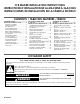


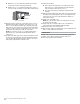
Table Of Contents
- Ice maker SAFETY
- INSTALLATION INSTRUCTIONS
- Unpack the Ice Maker
- Vacation or Extended Time Without Use
- Location Requirements
- Electrical Requirements
- Water Supply Requirements
- Drain Connection Requirements
- Door Reversal
- Drain Pump Installation (on some models)
- Connect Water Supply
- Leveling and Securing
- Custom Wood Panel
- Connecting the Drain
- Auxiliary Grill Installation
- Deep Clean
- SÉCURITÉ DE LA MACHINE À GLAÇONS
- INSTRUCTIONS D’INSTALLATION
- Déballage de la machine à glaçons
- Vacances ou longue période d’inutilisation
- Exigences d’emplacement
- Spécifications électriques
- Spécifications de l’alimentation en eau
- Exigences concernant le raccordement au drain
- Inversion de la porte
- Installation de la pompe de vidange (sur certains modèles)
- Raccordement à la canalisation d’eau
- Mettre de niveau et sécuriser
- Panneau de bois personnalisé
- Raccordement de la vidange
- Installation de la grille auxiliaire
- Nettoyage en profondeur
- SEGURIDAD DE LA FÁBRICA DE HIELO
- INSTRUCCIONES DE INSTALACIÓN
- Cómo desempacar la máquina de hielo
- Vacaciones o tiempo prolongado sin uso
- Requisitos de ubicación
- Requisitos eléctricos
- Requisitos del suministro de agua
- Requisitos para la conexión del desagüe
- Cambio del sentido de apertura de la puerta
- Instalación de la bomba de desagüe (en algunos modelos)
- Conexión del suministro de agua
- Nivelado y asegurado
- Panel de madera personalizado
- Conexión del desagüe
- Instalación de la rejilla auxiliar
- Limpieza intensa

12 13
3. Using pliers, remove the hinge covers from the top and
bottom hinges.
NOTE: Save the hinge covers for future use. Reinstall the
hinge covers if product is removed from cabinet installation.
4. For custom panel installation, install the door panel according
to the instructions in the “Custom Wood Panel” section.
5. Use ice maker leveling legs to align ice maker door to the
adjacent cabinet opening.
6. Slide ice maker into the cabinet while managing the utility
connection positions behind the ice maker. Be sure to cover
the oor with cardboard or hardboard to avoid damaging it.
IMPORTANT: For the custom panel model ush install, the ice
maker utility connections must be routed out through the slot
in the ice maker rear panel. Any time ice maker is removed for
service, do the same process when placing the unit back in
the cabinets.
7. Be sure that the ice maker is at desired depth. Secure the top
and bottom hinges to the side of the cabinet using wood
screws.
8. Attach the cabinet brackets (provided with ice maker) to the
holes in the front of ice maker as shown in the illustration.
Attach the cabinet brackets to the side of the cabinet with
wood screws.
NOTE: For the custom wood panel installation, continue
installation at step 7 of “Custom wood panel installation.”
WARNING
Excessive Weight Hazard
Use two or more people to move and install ice maker.
Failure to do so can result in back or other injury.
A
A. Cabinet bracket
5. Water inlet tube is located on the rear side of the ice maker as
shown in "Rear View" illustration. Bend the copper tubing to
match with water line inlet. Leave the coil of copper tubing as
it is to allow the ice maker to be pulled out of the cabinet or
away from the wall for service.
Rear View
6. Remove and discard the short, plastic tube from the end of
the water line inlet.
7. Thread the nut onto the end of the tubing. Tighten the nut by
hand. Then tighten it with a wrench two more turns. Do not
overtighten.
NOTE: To avoid rattling, be sure the copper tubing does not
touch the cabinet’s side wall or other parts inside the cabinet.
8. Install the water supply tube clamp around the water supply
line to reduce strain on the coupling. For custom panel
models, skip this step.
9. Turn shutoff valve ON.
10. Check for leaks. Tighten any connections (including
connections at the valve) or nuts that leak.
Leveling and Securing
It is important for the ice maker to be level in order to work
properly. Depending upon where you install the ice maker, you
may need to make several adjustments to level it. You may also
use the leveling legs to lower the height of the ice maker for
undercounter installations.
Tools Needed
Gather the required tools and parts before starting installation.
■ Level
■ Adjustable wrench
NOTE: It is easier to adjust the leveling legs if you have another
person to assist you.
1. Move the ice maker in front of its nal location. Be sure
to cover the oor with cardboard or hardboard to avoid
damaging it.
NOTE: If this is a built-in installation, move the ice maker as
close as possible to the nal location.
2. Remove the screws attaching top and bottom hinge covers
using an 3/16" hex driver.
A
C
B
A. Copper tubing
B. Water supply tube clamp
C. Inlet water tube clamp and
supply line connector for
standard model
D. Inlet water tube for custom
panel model
D
DAB C
A. Line to ice maker
B. Compression nut
C. Compression sleeve
D. Supplied line from ice maker
WARNING
Excessive Weight Hazard
Use two or more people to move and install ice maker.
Failure to do so can result in back or other injury.
Crush Hazard
Articulated hinges are self closing and many pinch
points exist prior to cabinet installation.
Do not remove hinge covers until product is ready to
be installed.
Failure to follow these instructions can result in crush,
cut, or pinch injuries.
WARNING
A
A. Hinge cover