
Installation Instructions

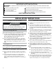


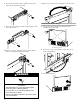


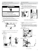
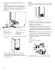
Table Of Contents
- Ice maker SAFETY
- INSTALLATION INSTRUCTIONS
- Unpack the Ice Maker
- Vacation or Extended Time Without Use
- Location Requirements
- Electrical Requirements
- Water Supply Requirements
- Drain Connection Requirements
- Door Reversal
- Drain Pump Installation (on some models)
- Connect Water Supply
- Leveling and Securing
- Custom Wood Panel
- Connecting the Drain
- Auxiliary Grill Installation
- Deep Clean
- SÉCURITÉ DE LA MACHINE À GLAÇONS
- INSTRUCTIONS D’INSTALLATION
- Déballage de la machine à glaçons
- Vacances ou longue période d’inutilisation
- Exigences d’emplacement
- Spécifications électriques
- Spécifications de l’alimentation en eau
- Exigences concernant le raccordement au drain
- Inversion de la porte
- Installation de la pompe de vidange (sur certains modèles)
- Raccordement à la canalisation d’eau
- Mettre de niveau et sécuriser
- Panneau de bois personnalisé
- Raccordement de la vidange
- Installation de la grille auxiliaire
- Nettoyage en profondeur
- SEGURIDAD DE LA FÁBRICA DE HIELO
- INSTRUCCIONES DE INSTALACIÓN
- Cómo desempacar la máquina de hielo
- Vacaciones o tiempo prolongado sin uso
- Requisitos de ubicación
- Requisitos eléctricos
- Requisitos del suministro de agua
- Requisitos para la conexión del desagüe
- Cambio del sentido de apertura de la puerta
- Instalación de la bomba de desagüe (en algunos modelos)
- Conexión del suministro de agua
- Nivelado y asegurado
- Panel de madera personalizado
- Conexión del desagüe
- Instalación de la rejilla auxiliar
- Limpieza intensa

3
Model Identication:
Standard Model Utilities
Custom Panel Model Utilities
Utility Slot/Cutout Location Zone
Dimension
A 9" (22.9 cm)
B 8" (20.3 cm)
C 7" (17.8 cm)
Diameter of the hole D 2" (5 cm)
■ Custom Panel ice maker models have been designed for ush
install in instances where the power supply, water supply, and
drain are located in adjacent cabinetry.
■ For installation of product with utilities behind the ice maker,
ush install may not be achieved.
■ Refer “Custom Panel Model Utilities” illustration and table
below it for utility slot/hole cutout location.
Electrical Requirements
Before you move your ice maker into its nal location, it is
important to make sure you have the proper electrical connection:
A 115 V, 60 Hz, AC only, 15 or 20 A electrical supply, properly
grounded in accordance with the National Electrical Code and
local codes and ordinances, is required.
It is recommended that a separate circuit, serving only your ice
maker, be provided. Use a receptacle which cannot be turned off
by a switch or pull chain.
IMPORTANT: If this product is connected to a GFCI (Ground
Fault Circuit Interrupter) equipped outlet, nuisance tripping of the
power supply may occur, resulting in loss of cooling. Ice quality
may be affected. If nuisance tripping has occurred, and if the
condition of the ice appears poor, dispose of it.
Recommended Grounding Method
The ice maker must be grounded. The ice maker is equipped with
a power supply cord having a 3 prong grounding plug. The cord
must be plugged into a mating, 3 prong, grounding-type wall
receptacle, grounded in accordance with the National Electrical
Code and local codes and ordinances. If a mating wall receptacle
is not available, it is the personal responsibility of the customer to
have a properly grounded, 3 prong wall receptacle installed by a
qualied electrician.
Standard model
B
A
A. Recommended location for electrical and plumbing xtures
B. Floor level
C
D
A
B
Electrical Shock Hazard
Plug into a grounded 3 prong outlet.
Do not remove ground prong.
Do not use an adapter.
Do not use an extension cord.
Failure to follow these instructions can result in death,
fire, or electrical shock.
WARNING
34"
(86.4 cm)
Min.
34¹⁄
2
"
(87.6 cm)
Max.
24"
(60.96 cm)
28¹⁄
2
"
(72.4 cm)
3¹⁄
2
"
(8.9 cm)
11¹⁄
2
"
(29.2 cm)
9"
(22.9 cm)
Custom panel model
7½"
(19.05 cm)
7½"
(19.05 cm)
Required zone
for utility hole/slot
cutout location