
Ice Maker User Manual


21
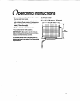
nit Wiring Diagrams
This model operates at 115 volts except for
the cutter grid circuit which operates at 8.5
volts at 1 amp.
The compressor runs at all times except
when the Bin Thermostat becomes satisfied
and opens the circuit. This de-energizes the
system except for the transformer and cutter
grid.
Under normal operating conditions, when
the evaporator reaches the preset tempera-
ture (+lO” to -3°F [-12” to -1 9”C], depending
on thickness of ice) the evaporator thermo-
stat opens, terminating operation of the fan
motor and pump motor. The hot gas sole-
noid and the water valve solenoid are
energized at this time and remain so until the
evaporator reaches 38” + 2°F (3” + 1%).
Electrical Shock Hazard
Disconnect power before servicing unit.
Failure to do so could result in electrical
shock.
NOTE:
Maximum fuse size: 15 amps.
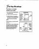
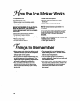
Check Operation
a0
Start the unit by turning the service
switch to “ON” and opening the line
water valve.
tH
NOTE:
Left is “OFF’ - Middle is “ON” -
Right is “CLEAN.” In ‘CLEAN” position,
only the pump operates.
d
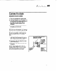
Check condenser fan to make sure it is
revolving. Check for airflow. Do not
insert hand into fan area.
d
Water will not enter pump pan until
freezing plate gets cold and machine
goes into a harvest cycle.
d
Check for even water flow over freez-
ing plate. Unit must be level for proper
operation.
d
Check for desired cube thickness and
after 24 hours adjust if necessary.
Maximum ice yield will be obtained
with ice thickness at l/i’ (13 mm) to %”
(16 mm).
d
Replace grille.
11