
Owner's Manual

9
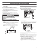
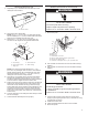
Install Range Hood
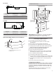
1. Depending on your installation, remove either top or rear
rectangular vent knockout.
2. Remove tape from damper fl ap.
NOTE: The 3
1
/
4
" x 10" (8.3 x 25.4 cm) rectangular damper
can be installed up to 1" (2.5 cm) on either side of the hood
center to accommodate off center duct work.
3. Attach the 3
1
/
4
" x 10" (8.3 x 25.4 cm) rectangular vent
connector to the range hood using sheet metal screws.
NOTE: If the wall cap is directly behind the 3
1
/
4
" x 10"
(8.3 x 25.4 cm) rectangular vent connector, check that the
damper and the wall cap do not interfere with each other.
Remove the damper from the 3
1
/
4
" x 10" (8.3 x 25.4 cm)
rectangular vent connector if they interfere.
4. Using two or more people, lift the hood into fi nal position.
Feed enough electrical wire through the 1/2" (12.7 mm)
ULlisted or CSA approved strain relief to make connections
in the terminal box. Tighten the strain relief screws.
5. Position the range hood so that the large end of the keyhole
slots are over the mounting screws. Then push the hood
toward the wall (for cabinet mounting) or allow the range
hood to slide down to the marked mounting height (for wall
mounting) so that the screws are in the neck of the slots.
Tighten the mounting screws, making sure the screws are
in the narrow neck of slots. (For wall mount, check that the
hood is level).
6. Connect ventwork to hood. Seal joints with clamps to make
secure and airtight.
7. Check that back draft dampers work properly.
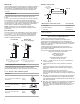
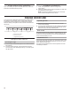
Make Electrical Connection
1. Disconnect power.
2. Use UL listed wire connectors and connect white wires (A)
together.
3. Use UL listed wire connectors and connect black wires (B)
together.
4. Connect green (or bare) ground wire from home power
supply to yellow-green ground wire (C) in terminal box using
UL listed wire connectors.
5. Install terminal box cover.
6. Check that all light bulbs are secure in their sockets.
7. Reconnect power.
A
A. Vent knockouts
A
B
C
D
C
B
E
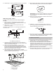
A. Top venting
B. Sheet metal screws
C. Hinge pin
D. Vent knockouts
E. Rear venting
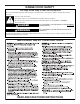
WARNING
Electrical Shock Hazard
Disconnect power before servicing.
Replace all parts and panels before operating.
Failure to do so can result in death or electrical shock.
A
B
C
D
E
F
A. White wires
B. Black wires
C. UL listed wire connector
D. Green (or bare) and yellow-green ground wire
E. Home power supply cable
F. UL listed or CSA approved 1/2" (1.3 cm) strain relief
WARNING
Electrical Shock Hazard
Electrically ground blower.
Connect ground wire to green and yellow ground wire
in terminal box.
Failure to do so can result in death or electrical shock.