
Owner's Manual
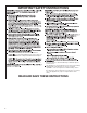
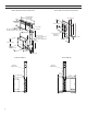
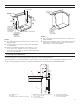
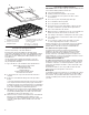
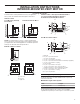
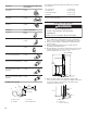
Table Of Contents
- Vent System Safety
- Installation Requirements
- Installation Instructions INTERIOR-MOUNTED VENT MOTOR
- INSTALLATION INSTRUCTIONS EXTERIOR-MOUNTED VENT MOTOR
- VENT SYSTEM USE
- VENT SYSTEM CARE
- Troubleshooting
- Wiring Diagrams
- Assistance or service
- SÉCURITÉ DU SYSTÈME DE VENTILATION
- EXIGENCES D'INSTALLATION
- INSTRUCTIONS D’INSTALLATION VENTILATEUR MONTÉ À L’INTÉRIEUR
- INSTRUCTIONS D’INSTALLATION VENTILATEUR MONTÉ À L’EXTÉRIEUR
- Méthodes d’évacuation
- Installation du conduit d’évacuation
- Achever l’installation
- Installation du ventilateur en ligne (type externe) du système d’extraction par le bas
- Raccordements électriques du système de ventilation en ligne
- Raccordement de l’alimentation électrique au système d’extraction par le bas
- Contrôle du fonctionnement
- UTILISATION DU SYSTÈME D’EXTRACTION
- ENTRETIEN DU SYSTÈME D’ÉVACUATION
- Dépannage
- SCHÉMA DE CÂBLAGE
- ASSISTANCE OU SERVICE

10
Vent Piece
3
1
/
4
" x 10" (8.3 cm x 25.4 cm)
Rectangular
3
1
/
4
" x 10" (8.3 cm x 25.4 cm)
90° elbow
5.0 ft
(1.5 m)
3
1
/
4
" x 10" (8.3 cm x 25.4 cm)
at elbow
12.0 ft
(3.7 m)
3
1
/
4
" x 10" (8.3 cm x 25.4 cm)
wall cap
0.0 ft
(0.0 m)
Vent Piece 6" (15.2 cm) Round
45° elbow 2.5 ft
(0.8 m)
90° elbow 5.0 ft
(1.5 m)
6" (15.2 cm) wall cap 0.0 ft
(0.0 m)
3
1
/
4
" x 10" (8.3 cm x 25.4 cm)
to 6" (15.2 cm) transition
4.5 ft
(1.4 m)
6" (15.2 cm) to 3
1
/
4
" x 10"
(8.3 cm x 25.4 cm) transition
1 ft
(0.3 m)
3
1
/
4
" x 10" (8.3 cm x 25.4 cm)
to 6" (15.2 cm) 90° elbow
transition
5.0 ft
(1.5 m)
6" (15.2 cm) to 3
1
/
4
" x 10"
(8.3 cm x 25.4 cm) 90° elbow
transition
5.0 ft
(1.5 m)
Example Vent System
The following example falls within the maximum vent length
of 35 ft (8.9 m).
Two 90° elbows = 10.0 ft (3 m)
One wall cap = 0.0 ft (0.0 m)
8 ft (2.4 m) straight = 8.0 ft (2.4 m)
Transition = 4.5 ft (1.4 m)
Length of 6" (15.2 cm) or 3
1
/
4
" x 10"
(8.3 cm x 25.4 cm) system
= 22.5 ft (6.8 m)
Install Vent System
1. Place cardboard or similar material on top of a at surface
where you can easily assemble the downdraft vent system.
2. Remove parts packages, downdraft vent, and blower box
from the carton.
3. Remove all shipping materials, tape, and lm from the
downdraft vent and blower box.
4. Measure distance “X” from the cabinet oor to the top of the
countertop. Subtract 28
1
/
2
" (72.4 cm) from distance “X” to
determine dimension “Y” (X - 28
1
/
2
" = Y).
5. Attach the support legs to the side of the vent box with
four 4 x 8 mm screws in each support leg. Adjust to dimension
“Y” from the bottom of the vent box to the bottom of the
support legs. Tighten screws.
A
B
C
6 ft
(1.8 m)
2 ft (0.6 m)
D
A. Blower motor
B. Transition
C. 90° elbows
D. Back draft damper
WARNING
Excessive Weight Hazard
Use two or more people to move and install
downdraft vent.
Failure to do so can result in back or other injury.
Cabinet floor
Top of countertop
Downdraft vent
“X”
“Y”
28¹⁄₂"
(73 cm)
A
B
Dim.
“Y”
C
A. Motor box
B. Support leg
C. 4 x 8 mm screws (4)