30" (76.2 CM) AND 36" (91.4 CM) RETRACTABLE (POP-UP) DOWNDRAFT VENT SYSTEM Installation Instructions and Use & Care Guide For questions about features, operation/performance, parts, accessories or service, call: 1-800-422-1230 In Canada, for assistance, installation and service, call: 1-800-807-6777 or visit our website at... www.kitchenaid.com or www.KitchenAid.
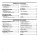
TABLE OF CONTENTS VENT SYSTEM SAFETY.................................................................3 INSTALLATION REQUIREMENTS ................................................5 Tools and Parts ............................................................................5 Location Requirements................................................................5 Electrical Requirements ...............................................................8 Venting Requirements...........................................
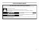
VENT SYSTEM SAFETY Your safety and the safety of others are very important. We have provided many important safety messages in this manual and on your appliance. Always read and obey all safety messages. This is the safety alert symbol. This symbol alerts you to potential hazards that can kill or hurt you and others. All safety messages will follow the safety alert symbol and either the word “DANGER” or “WARNING.
IMPORTANT SAFETY INSTRUCTIONS WARNING: TO REDUCE THE RISK OF FIRE, ELECTRIC SHOCK, OR INJURY TO PERSONS, OBSERVE THE FOLLOWING: ■ Use this unit only in the manner intended by the manufacturer. If you have questions, contact the manufacturer. ■ Before servicing or cleaning the unit, switch power off at service panel and lock the service disconnecting means to prevent power from being switched on accidentally.
INSTALLATION REQUIREMENTS Tools and Parts Gather the required tools and parts before starting installation. Read and follow the instructions provided with any tools listed here. Tools Needed ■ Jigsaw or keyhole saw ■ Drill ■ ¹⁄₈" (3 mm) drill bit for pilot holes ■ Pencil ■ Tape measure or ruler ■ Flat-blade screwdriver ■ Phillips screwdriver ■ ³⁄₈" (9.
Product Dimensions Models with interior-mounted blower motor Models with exterior-mounted blower motor Top trim widths: 30" (76.2 cm) 36" (91.4 cm) 4³⁄₄" (12.1 cm) 13¹⁄₂" (34.3 cm) retractable vent height 13¹⁄₈" (33.4 cm) 1¹⁄₂" (3.8 cm) 6⁹⁄₁₆" (16.7 cm) ³⁄₈" (0.95 cm) 27" (68.6 cm) for 30" (76.2 cm) vent 33" (83.8 cm) for 36" (91.4 cm) vent 10" (25.4 cm) diameter vent collar 5¹⁄₄"(13.3 cm) for 30" (76.2 cm) vent 8¹⁄₄"(21.0 cm) for 36" (91.4 cm) vent 28¹⁄₂" (72.4 cm) 13¹⁄₈" (33.4 cm) 8¹⁄₄" (21.
Cabinet Dimensions Interior-mounted blower motor model Exterior-mounted blower motor model 10" (25.4 cm) ¹⁄₂" (12.7 mm) minimum A= ¹⁄₂" (12.7 mm) minimum 21⁵⁄₁₆" (54.1 cm) 21⁵⁄₁₆" (54.1 cm) Cutouts are for 3¹⁄₄" x 10" (8.3 x 25.4 cm) rectangular or 6" (15.2 cm) round vent system. Locate power supply junction box at lower left hand rear corner of the cabinet. Locate power supply junction box at lower left hand rear corner of the cabinet.
Countertop Cutout Dimensions Chart B D C A A. ½" (12.7 mm) minimum to backsplash or rear wall B. ³⁄₄" (19.1 mm) maximum backsplash depth C. 27¹⁄₂" (69.9 cm) on 30" (76.2 cm) models 33¹⁄₂" (85.9 cm) on 36" (91.4 cm) models D. D = Measurement of cooktop rear overhang + 1¹³⁄₁₆" (46.2 mm) ■ Do not terminate the vent system in an attic or other enclosed area. ■ Do not use 4" (10.2 cm) laundry-type wall caps. ■ Do not install 2 elbows together. ■ Do not use plastic or metal foil vent.
INSTALLATION INSTRUCTIONS INTERIOR-MOUNTED VENT MOTOR Venting Methods Island Location—Vent System Installed Under a Concrete Slab Using PVC Sewer Pipe Determine which venting method is best for your application. Vent system can terminate either through the wall or floor. Island Location Front (Standard)-Mounted Blower Motor Front (Standard)-Mounted Blower Motor Rear-Mounted Blower Motor B A D E C M F G A H L A K I J Rear-Mounted Blower Motor A.
Calculating Vent System Length 3¼" x 10" (8.3 x 25.4 cm) rectangular vent is required from the blower motor box. It can be transitioned to 6" (15.2 cm) round vent if needed. Maximum Length of Vent System Vent Length 6" (15.2 cm) round 35 ft (8.9 m) 3¹⁄₄" x 10" (8.3 cm x 25.4 cm) 35 ft (8.9 m) To calculate the length of the system you need, add the equivalent feet (meters) for each vent piece used in the system. Vent Piece 3¹⁄₄" x 10" (8.3 cm x 25.4 cm) Rectangular 3¹⁄₄" x 10" (8.3 cm x 25.
Install Vent System 6. Measure distance “X” from the cabinet floor to the top of the countertop. Subtract 28¹⁄₂" from distance “X” to determine dimension “Y” (X - 28¹⁄₂ = Y). WARNING Excessive Weight Hazard Top of countertop Use two or more people to move and install downdraft vent. Failure to do so can result in back or other injury. 1. Place cardboard or similar material on top of a flat surface where you can easily assemble the downdraft vent system. 2.
Bottom Venting: NOTE: If installing the vent damper in the down position, a wall or roof cap with a damper at the exit end of the vent system is required. ■ Downdraft vent is shipped with blower in down venting position so no modification is required. ■ If rear mounting of the blower motor is not required, go to the “Complete Installation (Interior-Mounted Motor)” section. ■ To mount the blower motor to the rear side of the vent box, go to the “Rear Mounting - Blower Motor” section.
5. Remove the screws from the wire mounting plate. Complete Installation (Interior-Mounted Motor) NOTE: The downdraft vent system is supplied with a 3¹⁄₄" x 10" (8.3 x 25.4 cm) back draft damper and a 6" (15.2 cm) round vent transition with damper. Refer to “3¹⁄₄" x 10" (8.3 x 25.4 cm) back draft damper” or “6" (15.2 cm) round vent transition with damper,” depending upon the type of venting you are using. A A 3¹⁄₄" x 10" (8.3 x 25.4 cm) Back Draft Damper B C 1. Attach the 3¼" x 10" (8.3 x 25.
2. Remove 4 screws attaching the terminal box cover. 5. Drill 2 pilot holes through each of the undercounter mounting brackets into the underside of the countertop. Using 2 screws (not provided) of the appropriate length, mount the brackets to the countertop. IMPORTANT: Select a screw length that will not allow the screws to go through the countertop when tightened. B C A A. Terminal box cover 3. Determine which direction (front or rear) the home power supply cable will enter the terminal box.
Make Electrical Connections WARNING Check Operation 1. Push and hold the button on the top of the downdraft vent for a few seconds. The retractable section of the downdraft vent will rise, and the blower will start. Position the top trim over the retractable section and snap trim into place. Trim kits for matching your cooktop color are available from your dealer. For information on ordering, see the “Assistance or Service” section. Electrical Shock Hazard B Disconnect power before servicing.
INSTALLATION INSTRUCTIONS EXTERIOR-MOUNTED VENT MOTOR CAUTION: To reduce the risk of fire and electrical shock, install the downdraft only with remote blower systems that are sold by Whirlpool Corporation. Model numbers UXI0600DYS (600 cfm) and UXI01200DYS (1200 cfm). NOTE: Exterior-mounted vent motor installations require an approved in-line blower motor system. Model numbers UXI0600DYS (600 cfm) and UXI1200DYS (1200 cfm) are available from your dealer or authorized parts supplier.
Install Vent System 6. Measure distance “X” from the cabinet floor to the top of the countertop. Subtract 28¹⁄₂" from distance “X” to determine dimension “Y” (X - 28¹⁄₂" = Y). WARNING Excessive Weight Hazard Top of countertop Use two or more people to move and install downdraft vent. Failure to do so can result in back or other injury. 1. Place cardboard or similar material on top of a flat surface where you can easily assemble the downdraft vent system. 2.
Complete Installation (Exterior-Mounted Motor) 1. Remove 4 screws attaching the terminal box cover. 4. Drill 2 pilot holes through each of the undercounter mounting brackets into the underside of the countertop. Using 2 screws (not provided) of the appropriate length, mount the brackets to the countertop. IMPORTANT: Select a screw length that will not allow the screws to go through the countertop when tightened. B C A A A. Screws B. Backsplash C. Countertop A. Terminal box cover 2.
Prepare the In-line Blower System Install In-line Blower System NOTE: The blower motor housing can be mounted using 4 holes from either the inlet side or the outlet side of the blower. WARNING Outlet Side Excessive Weight Hazard A A Use two or more people to move and install in-line blower motor system. Failure to do so can result in back or other injury. 1. Using 2 or more people, move the in-line blower motor system to the mounting location. 2.
4. Locate the electrical terminal boxes in the in-line blower housing and downdraft vent. Remove the terminal box covers and set the covers and screws aside. Make Electrical Connections for In-Line Blower Motor System WARNING Electrical Shock Hazard B Disconnect power before servicing. A Replace all parts and panels before operating. A. Electrical terminal box B. Electrical knockout 5.
7. Use UL listed wire connectors and connect the gray wires (G) together. WARNING Make Electrical Power Supply Connection to Downdraft Vent WARNING Electrical Shock Hazard Electrically ground blower. Electrical Shock Hazard Connect ground wire to green and yellow ground wire in terminal box. Failure to do so can result in death or electrical shock. Disconnect power before servicing. Replace all parts and panels before operating. Failure to do so can result in death or electrical shock. 8.
4. Use UL listed wire connectors and connect white wires (B) together. WARNING Check Operation 1. Push and hold the button on the top of the downdraft vent for a few seconds. The retractable section of the downdraft vent will rise, and the blower will start. Position the top trim over the retractable section and snap trim into place. Trim kits for matching your cooktop color are available from your dealer. For information on ordering, see the “Assistance or Service” section.
VENT SYSTEM USE The retractable downdraft vent system is designed to remove smoke, cooking vapors and odors from the cooktop area. ■ For best results, the vent should be operating before cooking is started. ■ If you use large or tall utensils, place them on the large rear element or burner surface. ■ A higher heat setting than normally used may be needed when the downdraft vent is operating. ■ For gas cooktops, the downdraft vent system may affect the flame stability and cooking performance.
VENT SYSTEM CARE Surface of Downdraft Vent To avoid damaging the finish, clean downdraft vent with soap and water. Do not use scouring powder or abrasive solutions. Filters Frequently remove and clean the filter(s) in the retractable section of the downdraft vent. This will improve the operating efficiency of the downdraft vent system. Exterior Surfaces: To avoid damage to the exterior surface, do not use steel wool or soap-filled scouring pads. Always wipe dry to avoid water marks.
WIRING DIAGRAMS Interior-Mounted Blower Motor Y 7 Motor Specifications Power supply 120 VAC Frequency 60 Hz Wattage rating 420 W Amperage 3.7 A Motor Resistance BU/W 21.6 Ohms BU/R 18 Ohms BU/GY 14.3 Ohms BU/BK 9.8 Ohms Y/G S50 1˚ Speed W W 12 W BR BR 8 7 6 5 3 W 1 R BR 2˚ Speed R R 10 R 4 GY 2 GY R 3˚ Speed GY GY BK BK W 4˚ Speed BK BK BU 1 BR BK R GY N.C. N.O. Com BR 1 11 Neutral BU GY R 8 1 N.C. N.O. Com R R 2 BU 9 9 BR N.O. Com BR N.C.
NOTE: Wiring for external blower motor 8 6 11 9 7 W 9 5 W R 12 R 8 10 GY GY 1º Speed 2º Speed BK BK 3º Speed BU BU SEL0016521 4º Speed Common Exterior-Mounted Blower Motor 1 R GY BR BR N.C. BU BR BR GY Y/G N.C. W BK L N GY N.O. Com 3 N.C. 4 GY GY 3 6 GY G 26 N.O. Com R 5 N.O. Com BU NOTE: Wiring diagram is drawn with plenum in down position.
ASSISTANCE OR SERVICE When calling for assistance or service, please know the purchase date and the complete model and serial number of your appliance. This information will help us to better respond to your request. In Canada Call the KitchenAid Canada Customer eXperience Centre toll free: 1-800-807-6777 or visit our website at www.kitchenaid.ca.
KITCHENAID® VENTILATION WARRANTY LIMITED WARRANTY For one year from the date of purchase, when this major appliance is operated and maintained according to instructions attached to or furnished with the product, KitchenAid brand of Whirlpool Corporation or Whirlpool Canada LP (hereafter “KitchenAid”) will pay for Factory Specified Parts and repair labor to correct defects in materials or workmanship. Service must be provided by a KitchenAid designated service company.
SÉCURITÉ DU SYSTÈME DE VENTILATION Votre sécurité et celle des autres est très importante. Nous donnons de nombreux messages de sécurité importants dans ce manuel et sur votre appareil ménager. Assurez-vous de toujours lire tous les messages de sécurité et de vous y conformer. Voici le symbole d’alerte de sécurité. Ce symbole d’alerte de sécurité vous signale les dangers potentiels de décès et de blessures graves à vous et à d’autres.
IMPORTANTES INSTRUCTIONS DE SÉCURITÉ AVERTISSEMENT : POUR RÉDUIRE LE RISQUE D'INCENDIE, CHOC ÉLECTRIQUE OU DOMMAGES CORPORELS, RESPECTER LES INSTRUCTIONS SUIVANTES : ■ Utiliser cet appareil uniquement dans les applications envisagées par le fabricant. Pour toute question, contacter le fabricant.
EXIGENCES D'INSTALLATION Outils et pièces Exigences d'emplacement Rassembler les outils et pièces nécessaires avant d’entreprendre l’installation. Lire et observer les instructions fournies avec chacun des outils de la liste ci-dessous. REMARQUE : Le système d'extraction par le bas est installé directement derrière la table de cuisson. Installer d’abord le système d'extraction par le bas, puis la table de cuisson. IMPORTANT : Observer les dispositions de tous les codes et règlements en vigueur.
Dimensions du produit Modèles à ventilateur monté à l'intérieur Modèles à ventilateur monté à l'extérieur Largeurs de la garniture supérieure : 30" (76,2 cm) 36" (91,4 cm) 4³⁄₄" (12,1 cm) 13¹⁄₂" (34,3 cm) hauteur de l’évacuation rétractable 13¹⁄₈" (33,4 cm) 1¹⁄₂" (3,8 cm) 6⁹⁄₁₆" (16,7 cm) ³⁄₈" (0,95 cm) 27" (68,6 cm) pour une évacuation de 30" (76,2 cm) 33" (83,8 cm) pour une évacuation de 36" (91,4 cm) Raccord d’évacuation de 10" (25,4 cm) de diamètre 5¹⁄₄" (13,3 cm) pour une évacuation de 30" (7
Dimensions du placard Modèle avec ventilateur monté à l’intérieur Modèle avec ventilateur monté à l'extérieur 10" (25,4 cm) ¹⁄₂" (12,7 mm) minimum A= ¹⁄₂" (12,7 mm) minimum 21⁵⁄₁₆" (54,1 cm) 21⁵⁄₁₆" (54,1 cm) Les découpes correspondent à un circuit d’évacuation rectangulaire de 3¹⁄₄" x 10" (8,3 x 25,4 cm) ou rond de 6" (15,2 cm) Placer le boîtier de raccordement électrique dans l’angle arrière/gauche au bas du placard.
Plan de travail – Dimensions des ouvertures à découper IMPORTANT : Les plans de travail avec rebord avant arrondi ne sont pas recommandés pour ces installations. Certains modèles nécessitent un plan de travail de plus de 25" (63,5 cm); voir le tableau des dimensions de l'ouverture du plan de travail. Pour éviter une erreur, avant de découper une ouverture, tracer le périmètre des ouvertures à découper sur le plan de travail.
Spécifications électriques Exigences concernant l’évacuation Observer les dispositions de tous les codes et règlements en vigueur. S'assurer que l’installation électrique est correcte et qu'elle satisfait aux exigences de la plus récente édition de la norme National Electrical Code, ANSI/NFPA 70, ou de la norme CSA C22. 1-94, Code canadien de l’électricité, partie 1 et C22.2 No 0M91 (dernière édition) et de tous les codes et règlements en vigueur.
INSTRUCTIONS D’INSTALLATION VENTILATEUR MONTÉ À L’INTÉRIEUR Méthodes d’évacuation Déterminer la méthode d’évacuation la plus appropriée. La sortie à l’extérieur du circuit d’évacuation peut se faire à travers le plancher ou à travers un mur.
Pour calculer la longueur effective du circuit d’évacuation nécessaire, additionner les longueurs équivalentes (en pieds ou mètres) de tous les composants utilisés dans le circuit.
4. Installer sur la caisse du système d’extraction les équerres droite et gauche de montage sous le plan de travail. Insérer les encoches en trou de serrure dans les languettes guides et pousser les équerres vers le haut pour les fixer. 7. Fixer les pieds de soutien aux côtés de la caisse du système d’extraction avec 4 vis de 4 x 8 mm pour chacun. Les régler à la distance “Y” entre le bas de la caisse du système d’extraction et le bas des pieds de soutien. Serrer les vis. B A C A C Dim. “Y” D B A.
Sortie par le côté gauche ou le côté droit : 1. À deux personnes ou plus, poser l’arrière du système d’extraction par le bas face au sol. 2. Retirer les 4 vis du couvercle monté à l'avant de la caisse du moteur et les mettre de côté. Montage du ventilateur à l’arrière REMARQUE : Position de montage du ventilateur à l’arrière (côté opposé) possible pour les configurations en îlot. On peut déplacer la caisse du moteur du ventilateur du côté opposé (arrière) de la caisse du système d’extraction. 1.
5. Retirer les vis de la platine de montage du câble. Achever l’installation (Ventilateur monté à l’intérieur) A A REMARQUE : Le système d’extraction par le bas est livré avec un clapet anti-retour de 3¹⁄₄" x 10" (8,3 x 25,4 cm) et un raccord de transition pour conduit rond de 6" (15,2 cm) avec clapet. Se reporter à la section “Clapet anti-retour de 3¹⁄₄" x 10" (8,3 x 25,4 cm)” ou “Raccord de transition pour conduit rond de 6" (15,2 cm) avec clapet”, selon le type de circuit d’évacuation utilisé.
2. Ôter les 4 vis du couvercle du boîtier de connexion. 5. Percer 2 avant-trous à travers les équerres de fixation sous le plan de travail, dans la face inférieure du plan de travail. Avec 2 vis (non fournies) de la longueur adéquate, fixer les équerres au plan de travail. IMPORTANT : Choisir des vis d’une longueur adéquate pour ne pas traverser le plan de travail au serrage. B C A A. Couvercle du boîtier de connexion 3.
2. Faire passer le câble d’alimentation à travers le connecteur de conduit et dans le boîtier de connexion. AVERTISSEMENT Contrôle du fonctionnement 1. Appuyer pendant quelques secondes sur le bouton au sommet du système d’extraction par le bas. La partie rétractable du système d’extraction par le bas se lève, et le ventilateur se met en marche. Positionner la garniture supérieure sur la section rétractable; emboîter la garniture en place.
INSTRUCTIONS D’INSTALLATION VENTILATEUR MONTÉ À L’EXTÉRIEUR MISE EN GARDE : Afin de réduire le risque d’incendie ou de choc électrique, installer ce système d’extraction par le bas uniquement avec des ventilateurs installés à distance vendus par Whirlpool Corporation. Numéros de modèle UXI0600DYS (600 pi³/min) et UXI01200DYS (1200 pi³/min). REMARQUE : L’installation d’un ventilateur monté à l’extérieur nécessite un système de ventilation en ligne approuvé.
Installation du conduit d’évacuation AVERTISSEMENT 6. Mesurer la distance “X” entre le sol et le dessus du plan de travail. Soustraire 28¹⁄₂" de la distance “X” pour déterminer la distance “Y” (X - 28¹⁄₂" = Y). Risque du poids excessif Dessus du plan de travail Utiliser deux ou plus de personnes pour déplacer et installer le système d’extraction. Système d'extraction par le bas Le non-respect de cette instruction peut causer une blessure au dos ou d'autre blessure. 1.
Achever l’installation (Ventilateur monté à l’extérieur) 1. Ôter les 4 vis du couvercle du boîtier de connexion. 4. Percer 2 avant-trous à travers les équerres de fixation sous le plan de travail, dans la face inférieure du plan de travail. Avec 2 vis (non fournies) de la longueur adéquate, fixer les équerres au plan de travail. IMPORTANT : Choisir des vis d’une longueur adéquate pour ne pas traverser le plan de travail au serrage. B C A A A. Couvercle du boîtier de connexion 2.
Préparation du système de ventilation en ligne AVERTISSEMENT Risque du poids excessif Installation du système de ventilation en ligne REMARQUE : Le logement du ventilateur peut être monté en utilisant les 4 trous du côté de l'entrée ou de la sortie du ventilateur. Côté sortie Utiliser deux ou plus de personnes pour déplacer et installer le système du moteur du ventilateur en ligne. A A Le non-respect de cette instruction peut causer une blessure au dos ou d'autre blessure. 1.
4. Situer les boîtiers de connexion électrique dans la caisse du ventilateur en ligne et le système d’extraction par le bas. Retirer le couvercle des boîtiers de connexion et mettre de côté les couvercles et les vis. Raccordements électriques du système de ventilation en ligne AVERTISSEMENT Risque de choc électrique Déconnecter la source de courant électrique avant l'entretien. B A A. Boîtier de connexion électrique B. Opercule arrachable 5.
7. Raccorder les conducteurs gris (G) à l’aide de connecteurs de fils homologués UL. AVERTISSEMENT 3. Raccorder les conducteurs de couleurs correspondantes (noir et noir, blanc et blanc, etc.) à l’aide de connecteurs de fils homologués UL.
2. Situer le boîtier de connexion du système d’extraction par le bas. 5. À l’aide des connecteurs de fils (homologation UL), connecter le conducteur de terre vert (ou nu) du câble d’alimentation du domicile aux conducteurs de terre vert/jaune (A) du boîtier de connexion. 6. Installer le couvercle du boîtier de connexion. 7. Reconnecter la source de courant électrique. Contrôle du fonctionnement 1. Appuyer pendant quelques secondes sur le bouton au sommet du système d’extraction par le bas.
UTILISATION DU SYSTÈME D’EXTRACTION Le système d’extraction par le bas rétractable sert à éliminer la fumée, les vapeurs de cuisson et les odeurs issues de la table de cuisson. ■ Pour de meilleurs résultats, le système d’extraction doit être en marche avant d'entreprendre une cuisson. ■ Lors de l’emploi d’un récipient de grande taille, le placer sur le grand brûleur ou élément chauffant à l’arrière.
ENTRETIEN DU SYSTÈME D’ÉVACUATION Surface du système d’extraction par le bas Filtres Pour éviter d’endommager la finition, nettoyer les surfaces avec de l’eau savonneuse. Ne pas utiliser une solution de récurage ou un produit abrasif. Enlever et nettoyer fréquemment le(s) filtre(s) de la section rétractable du système d’extraction par le bas. Ceci optimisera l’efficacité de fonctionnement.
SCHÉMA DE CÂBLAGE Ventilateur monté à l'intérieur 7 Caractéristiques du moteur Alimentation 120 VCA Fréquence 60 Hz Puissance nominale 420 W Intensité 3,7 A Résistance du moteur BU/BL 21,6 ohms BU/R 18 ohms BU/GRIS 14,3 ohms BU/N 9,8 ohms JA/VE S50 BL BL MAR MAR GRIS MAR R N.O. Com MAR 5 N.F. 2 BL N N.O. Com R BU MAR MAR GRIS 1 N.F. GRIS 3 N.O. Com N.F. GRIS GRIS 3 6 GRIS BU SEL0015061 4 REMARQUE : Le schéma de câblage montre la fin de course en position basse.
REMARQUE : Câblage pour ventilateur à l'extérieur 8 6 9 BL BL 7 R R 5 GRIS GRIS 10 N N 9 11 8 12 1˚ vitesse 2˚ vitesse 3˚ vitesse BU BU SEL0016521 4˚ vitesse Commun Ventilateur monté à l'extérieur 1 R GRIS MAR MAR 5 N.O. Com MAR N.F. 1 2 JA/VE GRIS N.O. Com R BU MAR GRIS N.F. N.O. Com 3 N.F.
ASSISTANCE OU SERVICE Lors d’un appel pour assistance ou service, veuillez connaître la date d’achat, le numéro de modèle et le numéro de série complets de l’appareil. Ces renseignements nous aideront à mieux répondre à votre demande. Si vous avez besoin de pièces de rechange Si vous avez besoin de commander des pièces de rechange, nous vous recommandons d’employer uniquement les pièces spécifiées par l’usine.
GARANTIE DU SYSTÈME DE VENTILATION KITCHENAID® GARANTIE LIMITÉE Pendant un an à compter de la date d'achat, lorsque ce gros appareil ménager est utilisé et entretenu conformément aux instructions jointes à ou fournies avec le produit, la marque KitchenAid de Whirlpool Corporation ou Whirlpool Canada LP (ci-après désignées “KitchenAid”) paiera pour les pièces spécifiées par l'usine et la main-d'œuvre pour corriger les vices de matériaux ou de fabrication.
® W10342489E /™ ©2012 KitchenAid. Used under license in Canada. All rights reserved. Utilisée sous licence au Canada. Tous droits réservés.