36" (91.4 CM) AND 48" (121.9 CM) HOOD LINER Installation Instructions and Use & Care Guide For questions about features, operation/performance, parts, accessories or service, call: 1-800-253-1301 or visit our website at www.whirlpool.com In Canada, call 1-800-807-6777 or visit our website at www.whirlpool.
TABLE OF CONTENTS TABLE DES MATIÈRES RANGE HOOD SAFETY .................................................................2 INSTALLATION REQUIREMENTS ................................................4 Tools and Parts ............................................................................4 Location Requirements ................................................................4 Venting Requirements..................................................................5 Electrical Requirements ..................
IMPORTANT SAFETY INSTRUCTIONS WARNING: TO REDUCE THE RISK OF FIRE, ELECTRIC SHOCK, OR INJURY TO PERSONS, OBSERVE THE FOLLOWING: ■ Use this unit only in the manner intended by the manufacturer. If you have questions, contact the manufacturer. ■ Before servicing or cleaning the unit, switch power off at service panel and lock the service disconnecting means to prevent power from being switched on accidentally.
INSTALLATION REQUIREMENTS Tools and Parts Gather the required tools and parts before starting installation. Read and follow the instructions provided with any tools listed here. Location Requirements ■ Level ■ Drill ■ 1¼" (3 cm) drill bit ■ ¹⁄₈" (3 mm) drill bit ■ Pencil ■ Wire stripper or utility knife ■ Tape measure or ruler ■ Pliers ■ Caulking gun and weatherproof caulking compound IMPORTANT: Observe all governing codes and ordinances.
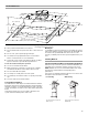
Product Dimensions 12³⁄₈" (31.4 cm) 11" (27.9 cm) 18" (45.7 cm) for 36" models 24" (61.0 cm) for 48" models 4¹³⁄₁₆" (12.2 cm) 11¹⁄₂" (29.2 cm) 10¹⁄₈" (25.7 cm) 22" (55.9 cm) 5¹⁄₁₆" (12.8 cm) 27⁵⁄₈" (70.1 cm) 29¹³⁄₁₆" (75.8 cm) 35⁷⁄₈" (91.1 cm) for 36" models 47⁷⁄₈" (121.6 cm) for 48" models Venting Requirements ■ Vent system must terminate to the outdoors. Makeup air ■ Do not terminate the vent system in an attic or other enclosed area. ■ Do not use 4" (10.2 cm) laundry-type wall caps.
Typical In-line Blower Motor System Venting Installations Electrical Requirements C A E D A D F B G A H A A. 10" (25.4 cm) round vent B. Mount on top of ceiling joists. C. Roof caps D. Plywood (optional for some installations) E. Mount on underside of roof rafters. F. Mount from cross-members tied to trusses. G. Duct horizontal; mount to cross-members tied to trusses. H. Wall cap Observe all governing codes and ordinances.
INSTALLATION INSTRUCTIONS Prepare Location ■ It is recommended that the vent system be installed before hood is installed. ■ Before making cutouts, make sure there is proper clearance within the ceiling or wall for exhaust vent. ■ Hood liner is to be installed 24" (61.0 cm) minimum for electric cooking surfaces, 30" (76.2 cm) minimum for gas cooking surfaces, to a suggested maximum of 36" (91.4 cm) above the cooking surface.
B Install Range Hood Liner The hood liner attaches to the hood support using four mounting screws and washers. NOTE: Hood support must be capable of supporting 75 lb (34 kg). 1. Using 2 or more people, lift the hood liner into place. 2. Install the hood liner using four 5 x 45 mm screws to the hood support and tighten securely. A D E C A. 4.2 x 8 mm screws (3) for motor support bracket B. 4.2 x 8 mm screws (2) for motor spring clip C. Motor support bracket D.
Install Hood Liner Internal Blower Motor 3. Run the power supply wires and connector from the range hood through the hole in the right end of the motor mounting plate. 1. Install the hood liner blower motor assembly inside the hood liner canopy with the wiring connection to the left for the single motor system and to the front or top for the dual motor system. A Single Blower Motor Assembly B A. Motor mounting plate hole B. Power supply wires and connector 4.
6. Attach power cord connector from the range hood to connector on wiring box. 5. Remove the screws that secure the blower motor assembly to the in-line blower housing and set them aside. 6. Pull the spring clip to release the blower motor assembly. Remove the blower motor assembly from the housing and place it on a covered surface. A A B C B A. Wiring box connector B. Power supply connector from range hood 7. Go to the “Make Electrical Power Supply Connection to Hood Liner” section. D A.
Complete Preparation Make Electrical Connections for In-Line Blower Motor System 1. Determine and make all necessary cuts for the vent system. IMPORTANT: When cutting or drilling into the ceiling or wall, do not damage electrical wiring or other hidden utilities. WARNING 2. Determine the location where the ¹⁄₂" (1.3 cm) wiring conduit will be routed through the ceiling or wall between the in-line blower and the hood liner. 3. Drill a 1¹⁄₄" (3.2 cm) hole at this location. 4.
WARNING NOTE: Connect the green (or green/yellow) ground wire from the wiring conduit to the green (or bare) ground wire from the home power supply using UL listed wire connectors (see the “Make Electrical Power Supply Connection to Hood Liner” section). B C D Electrical Shock Hazard Electrically ground blower. E Connect ground wire to green and yellow ground wire in terminal box. F G H A Failure to do so can result in death or electrical shock. 8.
E Complete Installation and Check Operation 1. Install grease filters. See the “Range Hood Care” section. 2. Check operation of the range hood blower and lights. See the “Range Hood Use” section. A B B A C C A F D A. White wires B. Black wires C. UL listed wire connectors D. Green, bare or yellow/green wires E. Home power supply F. UL listed or CSA approved ¹⁄₂" (1.3 cm) strain relief 3. Use UL listed wire connectors and connect black wires (B) together. 4.
RANGE HOOD USE The range hood is designed to remove smoke, cooking vapors and odors from the cooktop area. For best results, start the hood before cooking and allow it to operate several minutes after the cooking is complete to clear all smoke and odors from the kitchen. The hood controls are located on the underside of the range hood. Operating the fan 1. Move the fan switch to the “On” position to turn the fan ON. The fan will begin operating at the speed set on the fan speed switch. 2.
RANGE HOOD CARE Cleaning IMPORTANT: Clean the hood and grease filters frequently according to the following instructions. Replace grease filters before operating hood. Exterior Surfaces: To avoid damage to the exterior surface, do not use steel wool or soap-filled scouring pads. Always wipe dry to avoid water marks. Cleaning Method: ■ Liquid detergent soap and water, or all-purpose cleanser ■ Wipe with damp soft cloth or nonabrasive sponge, then rinse with clean water and wipe dry.
WIRING DIAGRAM Junction box N L Gnd Y-G SE112A BK W W W BU W BK BU 4 2 8 6 BK 2 1 3 5 Off 1 Light 2 4 Y 6 BU 2 6 2 4 6 7 BR 8 R 4 BR 2 On 3 Off 1 Fan BK 5 5 1 Fan speed GY R R On 3 Off 1 Fan speed 1 3 5 7 R R 2 3 1 W 4 GY BK 6 8 W 1 3 5 Fan speed W 2 3 7 R BK R R R R R BR Speed 1 Temperature sensor Speed 2 BK GY W Speed 3 BU 1 5 6 25uF 6 7 Y BK GY 8 9 10 Y/G 5 R 4 BU BR 3 Y 5 2 BR 4 1 BR 3 BU Y BU 25uF 4 3 2
ASSISTANCE OR SERVICE When calling for assistance or service, please know the purchase date and the complete model and serial number of your appliance. This information will help us to better respond to your request. If you need replacement parts If you need to order replacement parts, we recommend that you use only factory specified parts. Factory specified parts will fit right and work right because they are made with the same precision used to build every new appliance.
WHIRLPOOL CORPORATION MAJOR APPLIANCE WARRANTY LIMITED WARRANTY For one year from the date of purchase, when this major appliance is operated and maintained according to instructions attached to or furnished with the product, Whirlpool Corporation or Whirlpool Canada LP (hereafter “Whirlpool”) will pay for Factory Specified Parts and repair labor to correct defects in materials or workmanship. Service must be provided by a Whirlpool designated service company.
SÉCURITÉ DE LA HOTTE DE CUISINIÈRE Votre sécurité et celle des autres est très importante. Nous donnons de nombreux messages de sécurité importants dans ce manuel et sur votre appareil ménager. Assurez-vous de toujours lire tous les messages de sécurité et de vous y conformer. Voici le symbole d’alerte de sécurité. Ce symbole d’alerte de sécurité vous signale les dangers potentiels de décès et de blessures graves à vous et à d’autres.
IMPORTANTES INSTRUCTIONS DE SÉCURITÉ AVERTISSEMENT : POUR RÉDUIRE LE RISQUE D'INCENDIE, CHOC ÉLECTRIQUE OU DOMMAGES CORPORELS, RESPECTER LES INSTRUCTIONS SUIVANTES : ■ Utiliser cet appareil uniquement dans les applications envisagées par le fabricant. Pour toute question, contacter le fabricant.
EXIGENCES D'INSTALLATION Outils et pièces Exigences d'emplacement Rassembler les outils et pièces nécessaires avant d’entreprendre l’installation. Lire et observer les instructions fournies avec chacun des outils de la liste ci-dessous. IMPORTANT : Observer les dispositions de tous les codes et règlements en vigueur. Demander à un technicien qualifié d’installer la caisse de la hotte.
Dimensions du produit 12³⁄₈" (31,4 cm) 11" (27,9 cm) 18" (45,7 cm) - Modèle 36" (91,4 cm) 24" (61,0 cm) - Modèle 48" (121,9 cm) 4¹³⁄₁₆" (12,2 cm) 11¹⁄₂" (29,2 cm) 10¹⁄₈" (25,7 cm) 22" (55,9 cm) 5¹⁄₁₆" (12,8 cm) 27⁵⁄₈" (70,1 cm) 29¹³⁄₁₆" (75,8 cm) 35⁷⁄₈" (91,1 cm) - Modèle 36" (91,4 cm) 47⁷⁄₈" (121,6 cm) - Modèle 48" (121,9 cm) Exigences concernant l’évacuation ■ Le système doit décharger l'air à l'extérieur.
La sortie à l’extérieur du circuit d’évacuation peut se faire à travers le toit ou à travers un mur. Pour une sortie à travers un mur, on doit employer un raccord coudé à 90°.
INSTRUCTIONS D’INSTALLATION Préparation de l'emplacement ■ Il est recommandé d'installer le conduit de décharge avant de procéder à l'installation de la hotte. ■ Avant d’exécuter les découpages, vérifier la disponibilité d’un dégagement suffisant dans le plafond ou le mur pour le conduit d’évacuation. ■ La caisse de la hotte doit être installée à 24" (61 cm) min. des surfaces de cuisson électriques, 30" (76,2 cm) min.
B Installation de la caisse de la hotte La caisse de la hotte se fixe au support de hotte à l'aide des quatre vis de montage et des rondelles. REMARQUE : Le support de la hotte doit être capable de soutenir une charge de 75 lb (34 kg). 1. À l'aide d'au moins deux personnes, soulever la caisse de la hotte et l'installer. 2. Fixer la caisse de la hotte avec quatre vis de 5 x 45 mm au support de hotte et bien serrer. A D E C A. 3 vis de 4,2 x 8 mm pour le support du moteur B.
Installation du moteur du ventilateur interne de la caisse de la hotte 3. Faire passer les câbles d'alimentation et le connecteur de la hotte par le trou de l'extrémité droite de la plaque de montage du moteur. A 1. Installer le moteur du ventilateur de la caisse de la hotte à l'intérieur de l'auvent de la caisse, connexion du câblage à gauche pour le système à ventilateur unique et à l'avant ou au-dessus pour le système à deux ventilateurs. Ensemble à un seul moteur-ventilateur B A.
6. Relier le connecteur du cordon d'alimentation de la hotte au connecteur du boîtier de connexion. A B REMARQUE : L’ensemble moteur-ventilateur peut être retiré pour faciliter le montage du carter du moteur du ventilateur. Si l'on ne souhaite pas retirer l’ensemble moteur-ventilateur, passer à “Installation du système de ventilation en ligne” dans cette section. 4. Débrancher la prise électrique du moteur de l'ensemble moteur-ventilateur. 5.
3. Fixer le carter du moteur du ventilateur en ligne à l’emplacement de montage avec quatre vis de montage et rondelles 6 x 80 mm. 4. Réinstaller l’ensemble moteur-ventilateur s’il a été enlevé et le fixer avec les vis enlevées précédemment. 5. Rebrancher le cordon de la fiche électrique du moteur au connecteur de l’ensemble moteur-ventilateur s’il a été enlevé. Réalisation des connexions électriques du système du moteur du ventilateur en ligne AVERTISSEMENT Achever la préparation 1.
AVERTISSEMENT Risque de choc électrique Relier le ventilateur à la terre. Brancher le fil relié à la terre au fil vert et jaune relié à la terre dans la boîte de la borne. Le non-respect de ces instructions peut causer un décès ou un choc électrique. 4. Acheminer les extrémités des fils à parti de l’ensemble de connexion à 6 fils à travers le serre-câble ¹⁄₂" (1,3 cm), en laissant suffisamment de longueur pour effectuer les connexions de câblage. Serrer les vis du serre-câble. 5.
AVERTISSEMENT Réalisation des connexions de l’alimentation électrique à la caisse de la hotte AVERTISSEMENT Risque de choc électrique Relier le ventilateur à la terre. Brancher le fil relié à la terre au fil vert et jaune relié à la terre dans la boîte de la borne. Risque de choc électrique Déconnecter la source de courant électrique avant l'entretien. Replacer pièces et panneaux avant de faire la remise en marche. Le non-respect de ces instructions peut causer un décès ou un choc électrique. 1.
UTILISATION DE LA HOTTE La hotte de cuisinière est conçue pour extraire fumée, vapeurs de cuisson et odeurs de la zone de la table de cuisson. Pour obtenir les meilleurs résultats, mettre le ventilateur de la hotte en marche avant d’entreprendre une cuisson, et laisser le ventilateur fonctionner pendant plusieurs minutes après l’achèvement d’une cuisson pour pouvoir évacuer de la cuisine toute trace d’odeur de cuisson, vapeur ou fumée. Les commandes de la hotte sont situées sous celle-ci.
ENTRETIEN DE LA HOTTE Nettoyage IMPORTANT : Nettoyer fréquemment la hotte et les filtres à graisse en suivant les instructions suivantes. Réinstaller les filtres à graisse avant de faire fonctionner la hotte. Surfaces externes : Afin d'éviter d'endommager la surface externe, ne pas utiliser de tampons en laine d'acier ou de tampons à récurer savonneux. Toujours essuyer pour éviter de laisser des marques d'eau. Méthode de nettoyage : ■ Savon détergent liquide et eau, ou produit de nettoyage polyvalent.
SCHÉMA DE CÂBLAGE Boîtier de connexion Neu L Terre JA-VE SE112A N BL BL BL BU BL R N BU Marche Arrêt 2 1 1 5 7 3 Arrêt 1 Lampe 2 8 6 2 4 JA 4 N 6 R 2 3 Ventilateur BU 5 MAR 1 4 6 2 4 6 3 Vitesse du ventilateur N 8 BL R 5 1 GRIS R R R Marche Arrêt 1 3 5 7 Vitesse du ventilateur 2 4 6 GRIS BL N 8 2 3 1 MAR 1 3 5 BL 2 3 7 Vitesse du ventilateur R N R R R R MAR Vitesse 1 Capteur de température Vitesse 2 N GRIS BL Vitesse 3 BU 1 4 5
ASSISTANCE OU SERVICE Lors d’un appel pour assistance ou service, veuillez connaître la date d’achat, le numéro de modèle et le numéro de série complets de l’appareil. Ces renseignements nous aideront à mieux répondre à votre demande. Si vous avez besoin de pièces de rechange Si vous avez besoin de commander des pièces de rechange, nous vous recommandons d’employer uniquement les pièces spécifiées par l’usine.
GARANTIE DES GROS APPAREILS MÉNAGERS WHIRLPOOL CORPORATION GARANTIE LIMITÉE Pendant un an à compter de la date d'achat, lorsque ce gros appareil ménager est utilisé et entretenu conformément aux instructions jointes à ou fournies avec le produit, Whirlpool Corporation ou Whirlpool Canada LP (ci-après désignées “Whirlpool”) paiera pour les pièces spécifiées par l'usine et la main-d'œuvre pour corriger les vices de matériaux ou de fabrication.
W10331011B ©2011 Whirlpool Corporation. 2/11 All rights reserved. ® Registered Trademark/TM Trademark of Whirlpool, U.S.A., Whirlpool Canada LP Licensee in Canada Printed in Mexico Tous droits réservés. ® Marque déposée/TM Marque de commerce de Whirlpool, U.S.A.