
Installation guide

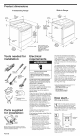

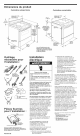

Product dimensions
Freestanding Range
Slide=in Range
30 l_
30" _ (78.2cm)
(78.2 cm) cooktop
8-1/4" cooktop I"'-I 1-1/2"
(21 cm) (3.8 cm) width
"_- 1" (2.5 cm)
spacer
27-3/4"
(70.5 cm)
depth with _
handle
44-3/8"
(112.7 cm)
overall
height
36"
(91.4 cm)
cooktop
height
with feet
loosened
1=!/2
turns
30" (78.2 cm) width
38" (9!.4 cm)
cooktop height
with feet 22-5/8"
loosened (67.5 cm)
1-1/2 turns
(2.5cm)
(86.4cm)
When installed in a 24" depth with
(61 cm) base cabinet with handle
25" (63.5 cm) cooktop --
front of oven door
protrudes !-7/8" (4.8 cm)
beyond 24" (61 cm) base
cabinet.
30"
(78.2 cm)
width
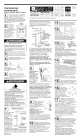
Tools needed for
installation:
level v_ _
ri
flat-blade
screwdriver or
5/16" nut
driver
(
hammer
3/8"
ratchet
safety
s
_ pliers J
wrench
measuring tape
Parts supplied
for installation:
anti-tip
bracket
2 plastic
anchors
(#10 x %1/2")
(Bracket must be securely mounted to sub-floor.
Thickness of flooring may require longer screws to
anchor the bracket to sub-floor.)
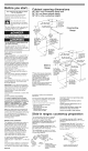
Panel B
Electrical
requirements
Electrical Shock Hazard
Electrically ground range.
Failure to follow these instructions
can result in death, fire, or electrical
shock.
if codes permit and a separate ground
wire is used, it is recommended that a
qualified electrician determine that the
ground path is adequate.
Do Not ground to a gas pipe.
Check with a qualified electrician if you
are not sure range is grounded.
Do Not have a fuse in the neutral or
ground circuit.
When a four-wire or three-wire, single- phase,
120/240-volt, 60-Hz, AC-only, electrical supply
is available, a 50-ampere maximum circuit
protection is required, (or, if specified on the
model/serial rating plate, when a four-wire or
three-wire, single-phase 120/208-volt, 60 Hz,
AC-only electrical supply is available, a 40-
ampere maximum circuit protection is
required), fused on both sides of the line. A
time-delay fuse or circuit breaker is
recommended. The model/serial rating plate
is located on the oven frame behind the
drawer.
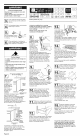
CONNECTION AT CONNECTION BLOCK
MUST BE COPPERWIRE ONLY.
if the house has aluminum wiring, follow the
procedure below:
a.) Connect a section of 8-gauge, solid
copper wire to the connector block.
b.) Connect the aluminum wiring to the
added section of copper wire using
special connectors designed and
Underwriters Laboratories-listed for
joining copper to aluminum. Follow the
electrical connector manufacturer's
recommended procedure.
c.) Aluminum/copper connection must
conform with local codes and industry-
accepted wiring practice.
Wire sizes and connections must conform
to the requirements of the National Electrical
Code, ANSI/NFPA 70 -- latest edition* or
CSA Standard C22.1, Canadian Electrical
Code, Part 1 -- latest edition** and all local
codes and ordinances for the kilowatt rating of
the range.
This range should be connected directly to
the fused disconnect or circuit breaker box
through flexible, armored or non-metallic
sheathed, copper cable (with ground wire).
Locate the junction box to allow two to three
feet of slack in the line so that the range can
be moved if servicing is ever necessary. Do
Not cut the conduit.
A U.L.- or CSA-listed conduit connector
must be provided at each end of the power
supply cable (at the range and at the
junction box). Wires sizes (COPPER WIRE
ONLY) and connections must conform with
the rating of the range,
Copies of the standards listed may be obtained from:
* National Fire Protection Association
One Batterymarch Park
Quincy, Massachusetts 02269
** CSA International
850! East Pleasant Valley Rd.
Cleveland, Ohio 44131-5575
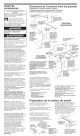
ow start...
With range in kitchen.
'-_ ut on safety glasses and gloves.
Remove shipping materials, tape
and protective film from range.
Keep cardboard bottom and shipping base
under range. Remove oven racks and parts
package from inside oven.
Take 4
cardboard
corners from
the carton.
Stack one
cardboard
corner on top spacers
of another, Repeat
with the other two corners, Place corners
lengthwise on the floor in back of range so
corners will support outer side edges of
range as shown,
cardboard
corners