The Klip Motor Driver User Guide Version 1.
Introduction Welcome to the Kitronik Klip Motor User Guide for the BBC micro:bit. This guide aims to provide all the essential information and instructions required to get started using, and teaching others about, the Klip Motor board.
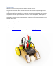
What it does The Klip Motor is an accessory board for the BBC micro:bit, expanding and augmenting its functionality. It has been designed to be completely solder and jumper wire free, instead enabling the use of crocodile clips or banana plugs on all of its input, output and power connections. It also includes an integrated 3 x AA battery pack, avoiding the need for extra trailing wires, and an easily accessible on/off switch.
Useful Accessories The Klip Motor board is compatible with a number Kitronik products already available, including motors, BBC micro:bit accessories and LEDs. The main accessory used across all projects involving the Klip Motor will be crocodile clips; having a variety of colours and lengths will be helpful (https://www.kitronik.co.uk/2407). There are some motors with add-on boards to make them ready for crocodile clip connections: • • Solderless TT Motor (https://www.kitronik.co.
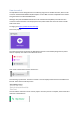
How to code it The Klip Motor board is designed to be controlled by programs on the BBC micro:bit, which can be created in the Microsoft MakeCode, MicroPython or other BBC micro:bit compatible environments. This guide focuses on Microsoft MakeCode. Although many standard MakeCode blocks can be used with the Klip Motor, Kitronik have also created a custom extension to accompany the board, which makes the control of motors and ZIP LEDs much easier. To begin, go to https://makecode.microbit.org/.
Clicking on this will reveal all the blocks available in the extension:
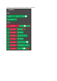
Within the extension, the blocks are split by motor control and ZIP LED control. A short description of the function of each block is given in the table below: Block Description This block starts a specific motor (either 1 or 2) spinning in a set direction (forward or reverse) at a set speed (0 to 100%). This block stops a specific motor spinning (either 1 or 2). This block sets up the ZIP LEDs attached to the Klip Motor board as a variable, enabling them to be controlled in the program.
This block moves all the colour settings for the ZIP LEDs along a certain number of ZIP LEDs in the string (the default is 1). The rotate block views the string of ZIP LEDs as a continuous loop, so the settings of the last ZIP LED will move to the first ZIP LED. This block sets the brightness of the ZIP LEDs to one of the four brightness options. These approximate to the following percentages: Dim = 10%, Normal = 50%, Bright = 80%, Super Bright = 100%.
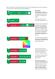
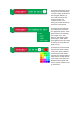
Example Program An example program using all the blocks in the Klip Motor Extension can be seen by following the link below: https://makecode.microbit.org/_LRfcowLAiero The program starts by setting up three ZIP LEDs to be attached to the Klip Motor board, with their brightness set to ‘Normal’. The first ZIP LED in the chain, LED 0, is set be red and then the changes are made visible. Nothing else will happen until either button A or B on the BBC micro:bit is pressed.
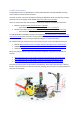
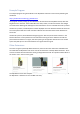
Example Projects Some example project setups are outlined in this guide to provide a starting point for using the Klip Motor. Writing programs to control the Klip Motor is dealt with in the ‘How to code it’ section. Example 1 – Driving two motors Equipment required: • • • • • 1 x Klip Motor board (https://kitronik.co.uk/5655) 1 x BBC micro:bit (https://www.kitronik.co.uk/5613) 2 x crocodile clip compatible motors (https://www.kitronik.co.uk/2594) 4 x crocodile clip leads (https://www.kitronik.co.
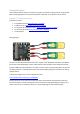
Example 2 – ZIP Hex Boards Equipment required: • • • • • 1 x Klip Motor board (https://kitronik.co.uk/5655) 1 x BBC micro:bit (https://www.kitronik.co.uk/5613) 3 x ZIP Hex boards (https://www.kitronik.co.uk/35140) 9 x crocodile clip leads (https://www.kitronik.co.uk/2407) 3 x AA batteries Wiring Diagram: Connect crocodile clip leads between the +V connections on the Klip Motor board and the first ZIP Hex board, then continue connecting along to the +V connections on the next two ZIP Hex boards.
Example 3 – STOP:bit Equipment required: • • • • • 1 x Klip Motor board (https://kitronik.co.uk/5655) 1 x BBC micro:bit (https://www.kitronik.co.uk/5613) 1 x STOP:bit (https://www.kitronik.co.uk/5642) 4 x crocodile clip leads (https://www.kitronik.co.
Example 4 – LAMP:bit Equipment required: • • • • • 1 x Klip Motor board (https://kitronik.co.uk/5655) 1 x BBC micro:bit (https://www.kitronik.co.uk/5613) 1 x LAMP:bit (https://www.kitronik.co.uk/5643) 4 x crocodile clip leads (https://www.kitronik.co.
Example 5 – ACCESS:bit Equipment required: • • • • • • 1 x Klip Motor board (https://kitronik.co.uk/5655) 1 x BBC micro:bit (https://www.kitronik.co.uk/5613) 1 x ACCESS:bit (https://www.kitronik.co.uk/5643) 3 x crocodile clip leads (https://www.kitronik.co.
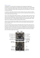
How it works - The Motor Driver Each motor is operated using two BBC micro:bit IO pins to provide control signals to a motor driver IC; pins 15 and 16 for Motor 1 and pins 13 and 14 for Motor 2. The signals from the BBC micro:bit use a technique called Pulse Width Modulation (PWM) to control the voltage seen across the motors, which then controls their speed. The PWM signals are square waves which have the ‘ON’ and ‘OFF’ times set to a particular ratio, known as the duty cycle.