
User Guide


Example 2 – ZIP Hex Boards
Equipment required:
• 1 x Klip Motor board (https://kitronik.co.uk/5655)
• 1 x BBC micro:bit (https://www.kitronik.co.uk/5613)
• 3 x ZIP Hex boards (https://www.kitronik.co.uk/35140)
• 9 x crocodile clip leads (https://www.kitronik.co.uk/2407)
• 3 x AA batteries
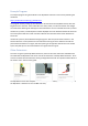
Wiring Diagram:
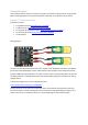
Connect crocodile clip leads between the +V connections on the Klip Motor board and the first ZIP
Hex board, then continue connecting along to the +V connections on the next two ZIP Hex boards.
Next, connect crocodile clip leads between the GND connections on the Klip Motor board and first
ZIP Hex board, then continue connecting along to the GND connections on the next two ZIP Hex
boards. Finally, connect crocodile clip leads between the ZIP output on the Klip Motor board and the
IN connection on the first ZIP Hex board, then continue connecting the OUTs to INs on the next two
ZIP Hex boards.
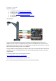
Program a BBC micro:bit (explained in the ‘How to code it’ section of this guide) and the slot this into
the edge connector on the Klip Motor board with the LED display facing up (as shown in the wiring
diagram above).
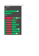
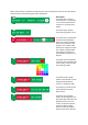
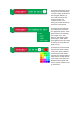
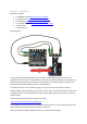
A short test program can be found using the link below:
https://makecode.microbit.org/_Kii63F9VY6yt
Pressing button A on the micro:bit will turn the lights green, pressing button B will turn them blue,
and pressing both A and B together will turn them off.
(Note: The example program given in the ‘How to code it’ section of this guide controls a
combination of examples 1 and 2)