
User Guide


How it works - The Motor Driver
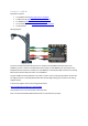
Each motor is operated using two BBC micro:bit IO pins to provide control signals to a motor driver
IC; pins 15 and 16 for Motor 1 and pins 13 and 14 for Motor 2. The signals from the BBC micro:bit
use a technique called Pulse Width Modulation (PWM) to control the voltage seen across the
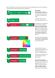
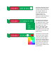
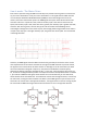
motors, which then controls their speed. The PWM signals are square waves which have the ‘ON’
and ‘OFF’ times set to a particular ratio, known as the duty cycle. If the ‘ON’ and ‘OFF’ times are
equal, then the duty cycle is 50%, if the ‘ON’ time is greater, then the duty cycle is greater than 50%,
and if the ‘OFF’ time is greater, then the duty cycle is less than 50%. As the PWM signals are
controlling the voltage seen at the motor outputs, the average power being provided to the motors
is equal to the duty cycle. The higher the duty cycle, the greater the motor speed. This is illustrated
in the diagram below:
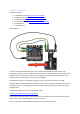
However, the PWM signals from the BBC micro:bit do not go directly to the motors as the current
draw requirements for the motors would be far too high for the BBC micro:bit to provide. Instead,
the signals control a motor driver IC which contains an ‘H-bridge’ circuit for each motor (so called
due to the schematic looking like a capital ‘H’). They have four Field Effect Transistors (FETs),
operating as switches, which are controlled in pairs – in this case, a pair of FETs for each of pins 13,
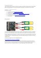
14, 15 and 16. The diagram below provides an example scenario for the Klip Motor board. For Motor
1, pin 15 drives a PWM control signal, which switches on its associated FETs; pin 16 is held at 0V,
which switches off its associated FETs. This enables the current flow through the motor, as shown by
the red arrows, turning the motor forwards. For Motor 2, the PWM signal is on pin 14 and pin 13 is
held at 0V. The current flow is the opposite of Motor 1, turning the motor in reverse. Driving the pins
16 and 14 with a PWM control signal would cause the motors to turn in the opposite direction.