
Installation Instructions

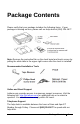
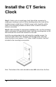
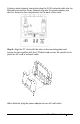
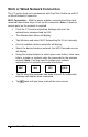
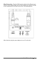
Table Of Contents
- THIS EQUIPMENT COMPLIES WITH FCC REQUIREMENTS
- Package Contents
- Install the CT Series Clock
- PayClock Online
- Using the CT Clock
- Employee Transactions
- Clocking IN/Out - Finger Sensor (CT72)
- Clocking IN/Out - Badge
- Clocking IN/Out - PIN
- Department Transfers - Finger Sensor (CT72)
- Department Transfers - Badge
- Department Transfers - PIN
- Amount Entries - Finger Sensor (CT72)
- Amount Entries - Badge
- Amount Entries - PIN
- Viewing Totals - Finger Sensor (CT72)
- Viewing Totals - Badge
- Viewing Totals - PIN
- Employee Transactions
- Supervisor Transactions
- Enrolling Fingers
- Administrator Functions
- Troubleshooting the CT Series
- Appendix A – Testing the Connection to PayClock Online
- Appendix B – Installing a Battery
- Appendix C – Adjusting Finger Sensitivity
- Appendix D – Bell Relay Connections
- Appendix E – Access Relay Connections
- Appendix F – Add/Edit/Delete Bell Events
- Blank Page

Install the CT Series Clock • 3
If using a wired network connection plug the RJ 45 network cable into the
Ethernet port and the Power Adapter plug into the power adapter port
which is located in the compartment on the back of the clock.
Step 3: Align the CT clock with the tabs on the mounting-plate and
secure the two together with the 2 Philips head screws. Be careful not to
pinch the AC cord or network cable.
When finished, plug the power adapter into an AC wall outlet.