
User Manual


4
6. Level adjustment - Channel 2
7. Indicator switch on/off Channel 3
8. LOOPBACK input
9. Level adjustment - Channel 3
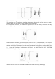
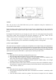
REAR PANEL
Figure 2
1. Output terminals – Channel 1 & 2
2. Input switch on/off Channel 3 (contacts open – channel on, the contacts are closed – channel
off)
3. Output terminals – Channel 3
4. AC power input (220V for European version)
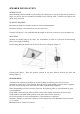
TRANSDUCER INSTALLATION
Since the DNG-2300 uses the TRN-2000, which is produced for the ANG-2000/2200, it is
recommended to follow the instructions stated in the User Manual of the ANG-2000/2200. For your
convenience, they are repeated below.
INTRODUCTION
An ideal installation would be accomplished during construction or remodeling where sensitive
points in the structure can be protected with transducers built into the building's structure. If this is
not possible, the transducers can be placed directly onto wall surfaces. If visual appearance is a
problem, the transducers should be disguised or covered accordingly.
QUANTITY REQUIRED
Determine the quantity of transducers needed by these recommendations:
WALLS - One placed every eight linear feet, centered between floor and ceiling. Mount on or within
6 inches of a stud.
FLOOR and CEILING - One centered on every 64 square feet. (Use the OMS-2000 speaker for drop
ceiling.)
WINDOWS - One placed on every major pane of glass within 6" of the corner.
DOORS - One placed adjacent to the center hinge on the doorframe.
Note: "Shielded Screen Rooms" are shielded against R.F. devices transmitting out of the room,