DVR-520 4-Channel Smart DVR Series with Removable HDD Bay User’s Manual
Copyright The documentation and the software included with this product are copyrighted 2005 by Advantech Co., Ltd. All rights are reserved. Advantech Co., Ltd. reserves the right to make improvements in the products described in this manual at any time without notice. No part of this manual may be reproduced, copied, translated or transmitted in any form or by any means without the prior written permission of Advantech Co., Ltd. Information provided in this manual is intended to be accurate and reliable.
Product Warranty (1 year) Advantech warrants to you, the original purchaser, that each of its products will be free from defects in materials and workmanship for one year from the date of purchase. This warranty does not apply to any products which have been repaired or altered by persons other than repair personnel authorized by Advantech, or which have been subject to misuse, abuse, accident or improper installation.
Declaration of Conformity CE This product has passed the CE test for environmental specifications when shielded cables are used for external wiring. We recommend the use of shielded cables. This kind of cable is available from Advantech. Please contact your local supplier for ordering information. CE This product has passed the CE test for environmental specifications. Test conditions for passing included the equipment being operated within an industrial enclosure.
Technical Support and Assistance 1. Visit the Advantech web site at www.advantech.com/support where you can find the latest information about the product. 2. Contact your distributor, sales representative, or Advantech's customer service center for technical support if you need additional assistance.
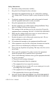
Safety Instructions 1. Read these safety instructions carefully. 2. Keep this User's Manual for later reference. 3. Disconnect this equipment from any AC outlet before cleaning. Use a damp cloth. Do not use liquid or spray detergents for cleaning. 4. For plug-in equipment, the power outlet socket must be located near the equipment and must be easily accessible. 5. Keep this equipment away from humidity. 6. Put this equipment on a reliable surface during installation.
20° C (-4° F) OR ABOVE 60° C (140° F). THIS COULD DAMAGE THE EQUIPMENT. THE EQUIPMENT SHOULD BE IN A CONTROLLED ENVIRONMENT. 16. CAUTION: DANGER OF EXPLOSION IF BATTERY IS INCORRECTLY REPLACED. REPLACE ONLY WITH THE SAME OR EQUIVALENT TYPE RECOMMENDED BY THE MANUFACTURER, DISCARD USED BATTERIES ACCORDING TO THE MANUFACTURER'S INSTRUCTIONS. The sound pressure level at the operator's position according to IEC 7041:1982 is no more than 70 dB (A).
11. Wird das Gerät über einen längeren Zeitraum nicht benutzt, sollten Sie es vom Stromnetz trennen. Somit wird im Falle einer Überspannung eine Beschädigung vermieden. 12. Durch die Lüftungsöffnungen dürfen niemals Gegenstände oder Flüssigkeiten in das Gerät gelangen. Dies könnte einen Brand bzw. elektrischen Schlag auslösen. 13. Öffnen Sie niemals das Gerät. Das Gerät darf aus Gründen der elektrischen Sicherheit nur von authorisiertem Servicepersonal geöffnet werden. 14.
Safety Precaution - Static Electricity Follow these simple precautions to protect yourself from harm and the products from damage. 1. To avoid electrical shock, always disconnect the power from your PC chassis before you work on it. Don't touch any components on the CPU card or other cards while the PC is on. 2. Disconnect power before making any configuration changes. The sudden rush of power as you connect a jumper or install a card may damage sensitive electronic components.
General Electrical Safety Guidelines Warning!: Follow the guidelines below to avoid possible damages to the system or injury to yourself: • Be aware of the locations of the power switches on the chassis and in the room, so you can disconnect the power supply if an accident occurs. • Take extra precautionary measures when working with high voltage components. It is not recommended to work alone. • Before removing or installing main system components, be sure to disconnect the power first.
General Safety Guidelines Warning!: Follow these rules to ensure general safety: • Keep the area around the DVR series clean and free of clutter. • To avoid injuries to the back, be sure to use your leg muscles, keep your back straight, and bend your knees, when lifting the system. • Avoid wearing loose clothing to preventing it from coming into contact with electrical circuits or being pulled into a cooling fan.
DVR-520 User’s Manual xii
Contents Chapter Chapter Chapter 1 DVR-520 Introduction .................................... 2 1.1 Front Panel ........................................................................ 3 1.2 Rear Panel ......................................................................... 4 Figure 1.2:Rear panel layout .......................................... 4 2 Remote DVR Installation ............................... 6 2.1 Video Output Connection (TV or LCD Monitor) ............. 6 2.
A.3.2 A.4 A.5 A.6 Playback ....................................................................... 39 DVR Management........................................................... 40 AVI File........................................................................... 41 Single Channel Scaler ..................................................... 42 Appendix B PC Viewer ...................................................... 44 B.1 Installing PC Viewer .......................................................
CHAPTER 1 2 DVR-520 Introduction This section introduces the Digital Video Recorder (DVR).
Chapter 1 DVR-520 Introduction The DVR-520 digital video recorder (DVR) is for recording/retrieving video streams from up to 4 channels at the same time. It adopts a digital image compression technology to compress the input channel video streams, and uses a HDD to record the compressed video stream. This user manual explains how to install, operate, and manage the DVR in your home. Hope you enjoy it and find it useful to protect your home or office.
1.1 Front Panel Figure 1.1: Front panel layout 1. z Recording button: press to start recording 2. Stop recording/playback button: press to stop recording/playback--the authorized password is requested upon stopping record (the defaut password is 555555: button 田 ) 3. Fast forward button: press to play the recorded video stream faster 4. /f Playback 5. Reverse: press to play backwards 6. Select button: press to change the setting value or enter a sub menu 7.
1.2 Rear Panel Figure 1.2: Rear panel layout 12 1 3 4 2 5 6 7 8 9 10 11 1. S-Video 2. Video output 3. Monitor: Second Video output 4. Video input 5. Video loop-through 6. Sensor input/alarm output: 4 sensor inputs and one alarm output 7. NTSC/PAL switch 8. DC-in (12 Volts) 9. Audio-in/out 10. LAN (RJ-45) 11. Power switch 12. PC Link: USB device interface (2.
CHAPTER 2 2 DVR Installation This section explains the installation of the DVR-520 Digital Video Recorder (DVR).
Chapter 2 Remote DVR Installation 2.1 Video Output Connection (TV or LCD Monitor) Please connect a TV or LCD monitor to the unit over the video output connector. The unit provides one S-Video input, two BNC connectors and one VGA output. Figure 2.
2.2 Video Input Connection (Camera) Please connect camera to the unit over the video input connector. The unit provides four BNC connectors. The camera installation procedures are as follows: 1. Connect the video signal line: Connect the video signal line to the unit. 2. Connect the camera power line: Connect the camera’s adaptor to the camera, and plug in the adaptor. The complete connection with a camera is as shown below. Figure 2.
2.3 Sensor Installation The unit provides four sensor inputs for four channels. The sensor installation is as follows. The maximum power requirement of the sensor device is up to 1.5 V @ 50 mA. 1. Connect the sensor signal line: Connect the video signal line to the unit. The Sensor signal terminal is at the unit’s back panel. 2. Connect the sensor power adaptor jack into the sensor, and plug in the adaptor. Figure 2.
2.4 Alarm Installation The unit provides one internal switch for sounding an alarm when the sensor is activated due to the unwanted entrance of an unknown visitor. The switch is open in the normal state, but when the alarm is activated, the switch is closed to power the alarm. The circuitry is shown below. There are two simple steps for the installation of the alarm. 1. Prepare the power supply: The alarm needs a power supply, the power supply comes with the alarm. 2.
DVR-520 User’s Manual 10
CHAPTER 3 2 Powering Up the Unit This section shows the power up screens of the Digital Video Recorder (DVR).
Chapter 3 Powering Up the Unit 3.1 On-Screen Display After the unit is properly installed, it is ready to record and play. Apply power and switch on. Note: Make sure the HDD is powered off before removing the drive After the unit is powered on, the unit checks the HDD for several seconds, then displays the following screen. Figure 3.1: HDD Checking in progress Figure 3.2: Real Time Display Mode The unit will enter into real-time display mode as shown above.
Notes: 1. Make sure the HDD is off before removing the drive. 2. Once you resume the initial setting, the right information will be displayed on the screen. Turn off the unit and restart.
OnScreen Display (OSD) Figure 3.
CHAPTER 4 2 Operation Guide This section explains the operation of the DVR-520 Digital Video Recorder (DVR).
Chapter 4 Operation Guide 4.1 Main Menu Press to display menu Operation Buttons press to display menu option. press to change menu field or change the unit’s configuration val- press to select menu item or confirm the selection. ues. Note: Please stop recording or playback before you enter into the OSD menu. You will be requested to enter a password to stop recording.
4.2 Camera Select The unit provides sixteen camera inputs. Every four channels are grouped for easy and prompt display operation. For example, Ch 1, Ch 2, Ch 3 and Ch 4 are set for Group 1; Ch 5, Ch 6, Ch 7 and Ch 8 are for Group 2 and so on. The unit provides 4 camera groups. You can use group select buttons on the front panel to select specified group for real-time display. You can use the channel display. button or group select buttons for different groups of Example: 1.
4.3 Record Select Selecting a group on this menu option is the same as selecting the “Group Select” option. Only the selected group will record real-time events during the recording period. 4.4 Record Mode There are two kinds of recording modes: 回 (each mode; full screen mode) and 田 (quad screen mode). when you select 回 mode, you can view the full-screen display of one specified channel. When you select 田 mode, a quad-screen will be displayed.
4.5 Record Frame Rate There are nine different frame rate settings for operation: 30 fps, 15 fps, 10 fps, 7 fps, 5 fps, 4 fps, 3 fps, 2 fps and 1 fps (The unit is set to 30 fps at the factory). Please use buttons on the front panel to select a mode and then enter to confirm the selection. Note: Recording Frame Rate: The higher the record frame rate, the more natural the look will be displayed on the screen in playback mode. The lower the record frame rate is, less space will be used on the HDD.
4.6 Video Quality The higher the video quality is, the more clear the image will be. Lower video quality means less space is used on the HDD. You can refer to Appendix C for the recording time vs. video quality settings table for your reference. 4.7 Record Schedule Enter into this option to change a recording schedule during a day (24hour period). Numbers above indicate the time duration of 24 hours. (T) Letter indicates recording. (S) Letter indicates sensor recording.
+SSSSSS----T T T T T T T S S S S S S + : : : : : 0 6 11 18 24 Note: Sensor Recording Installation: The unit provides four alarm inputs which can be configured as normally closed, normally open, motion detection + NC and motion detection + NO in the “SENSOR SETUP” menu option. After sensor configuration, please go back to the “RECORD SCHEDULE” menu to enable sensor recording. 4.8 Sub Menu Enter into this option to change password, time /date settings, and date format.
If the password was not accepted, the unit will automatically return to “SUB MENU”. Table 4.1: Front panel button definitions means “5” z means “6” 田 means “7” means ”8” means “B” /f means “C” means “D” 田 means “E” Time Set Enter this option to change the date and time. The unit provides yyyy/mm/dd or dd/mm/yyyy variants which reflect regional preferences.
4.9 Backup Through USB Port The unit provides one USB port for simple backup over a connection with a PC. Please use the following steps to successfully link: 1. Connect the USB cable between the unit and PC. 2. Select “LINK TO PC” under the submenu of the unit. The “linking” will take around 30 seconds. The connection is then ready for PC backup as “Linked” is indicated on the screen. 3. Open the PC viewer on the PC, after the PC identifies the unknown hardware device. 4.
Warning!: Please don’t press the “MENU” button during linking, it could lead to an unpredictable error on your PC. Note: Please refer to Appendix C for the PC viewer installation and operation guide. 4.10 Sequential Time Use this menu to specify each channel display dwell time. Dwell time settings range from 1 sec to 9 sec between displays for the 4 channels. Note: Please press to confirm the setting or press the 田 button to disable the setting.
4.11 Hard Disk Setup HARD DRIVE SETUP OVERWRITE ENABLED YES MASTER HDD SIZE 40000MB MASTER HDD USED 0MB 0% MASTER HDD FORMAT SLAVE HDD SIZE PRESS (¿À), THEN ( ) PRESS( ) TO EXIT Overwrite Enabled: If you choose “YES”, the unit will continue recording and overwrite the recorded data when the HDD’s space is full. If you choose “NO”, the unit will stop recording when the HDD’s space is full. Master HDD Size: Indicates the capacity of the primary HDD installed in the unit.
4.12 Sensor Setup Sensor Record Time: This controls the recording duration once the sensor is triggered. SENSOR SETUP SENSOR RECORD TIME ALARM OUT TIME MOTION SENSITIVE SETUP CHANNEL-1 TYPE:MOTION + CHANNEL-2 TYPE:MOTION + CHANNEL-3 TYPE:NORMAL CLOSE CHANNEL-4 TYPE:NOT INSTALLED PRESS (¿À), THEN PRESS( ) TO EXIT 15 20 N-C N-O ( ) Alarm Out Time: This controls how long (in seconds) the alarm sounds after being triggered. MOTION SENSITIVE SETUP Use this menu to adjust the sensitivity of each channel.
In normally open mode, if the cable between the sensor and the unit is cut by an intruder, the unit starts recording. In normally closed mode, if the cable between the sensor and the unit is cut by an intruder, the unit stops recording. 4.13 How to Operate Motion Detection Recording Follow the steps given below to activate motion-detection recording. 1. Please go to “SENSOR SETUP” menu as shown in the figure.
4.14 Network Setup 1. ACCEPT IP: Make sure this first option is set to YES. 2. MAC ADDRESS: Will not need to be altered. 3. *IP ADDRESS (a static IP address): Will need to be set to the DVR IP address you are planning to use to connect to the internet. 4. SUBNET MASK: Will need to be obtained from the routing device. 5. GATEWAY IP address (IP address A): Will need to be obtained from the routing device. 6. DVR ID ON LAN: Use the button to specify the DVR’s identification.
Note: 1. PC Minimum requirements for Networking: • CPU: 1 GHZ or above • System memory: 256 MB or above • VGA memory: 32 MB • OS: Windows 2000/XP 2. Please assign 14337, 14338 to the Port to install the DVR in a LAN with a static IP address under a router (with firewall) for sharing with other equipment like a PC.
4.15 Playback Please use the front panel buttons to operate various playback functions. Press the button. The playback time/events selection menu then appears on the screen. You can also press twice to directly start playing. You can either enter the specified time/date to playback or select the event or view the playback over PC. Notes: 1. Please stop recording before playback. 2. Because the events selection is the default setting, you need to press the button to switch to the time selection.
(reverse button): Press this button to play the recorded stream backwards. Note: The reverse playback speed depends on the fps, the number of recorded channels, and the video quality. (pause button): Press this button to pause the playback, or to advance a single frame at a time.
DVR-520 User’s Manual 32
APPENDIX 2 A Networking This section explains the networking details of the Digital Video Recorder (DVR).
Appendix A Networking This unit and the dedicated remote PC client software allows you to view live and recorded video over the internet from a remote location. You can also capture and convert video from the unit into an AVI file or JPEG file, and play the stored video later on. Please follow the instructions below to use PC Client. After you install PC Client software on your PC, the main window will appear. Figure A.
A.1 Connect PC to the DVR Click on the “Connect” option in the main window. Click to enter the DVR Client Connection Manager Click “Connect” to enter the “DVR Client connection manager” as shown above.
Specify the values in the various fields as given below. DVR IP: The DVR IP address is the IP address of the remote DVR. Password: The password is the same password used for formatting the DVR’s hard drive. The default value is 111111. Nickname: If you have configured the DHCP settings in the DVR, you can connect to the DVR by clicking on “Search DVR”. There will be a list of DVRs in the Nickname list box. Select the one you want to connect to from the list. Click “OK” to create the connection.
To disconnect, simply click “Disconnect”. To close the application, click “Close Window” button.
A.2 DVR Control The panel shown in the following figure operates exactly as the DVR operation buttons to allow you to remotely control the DVR for live view, record and playback functions.
A.3 Capture and Playback on your PC A.3.1 Capture Video Data When you click the “REC” button, the DVR client will start to record the incoming video onto your PC’s hard disk. The DVR client creates a “stream_files” folder where the file is located. When the client is recording, the Capture & Play status indicator shows “REC” as the current status. A.3.2 Playback After recording is finished, click the “Play” button to play the recorded video stream.
A.4 DVR Management This option enables you to remotely adjust the DVR’s operation settings: Video Quality, Record Frame Rate, Alarm On Duration, Alarm Record Duration, Input Channels, Record Channels, DVR system time setting and Record Schedule. All these settings operate as they would directly on the DVR itself. Note: The record mode change can be made only on the DVR, to allow the display to show the current DVR record mode on connection. .
A.5 AVI File Click on the “AVI save as” button to convert the desired video data into an AVI file. You will see the following dialog box for saving the AVI file. Click on this button to convert the real-time video data or the recorded data into an AVI file After specifying the file name and confirming, click on “Backup to AVI” to start the conversion.
A.6 Single Channel Scaler The single channel scaler is functional only in single channel mode. If you are viewing a single channel, you can scale up/down by selecting these options.
APPENDIX 2 B PC Viewer This section explains the PC Viewer of the Digital Video Recorder (DVR).
Appendix B PC Viewer B.1 Installing PC Viewer Please follow the steps given below to complete the installation of PC Viewer.
You can access video data via the connection between the PC and DVR or directly install the HDD into a PC. Please install the PC Viewer software onto your PC and start the program. Note: This software currently supports Windows 2000 and Windows XP. You will see a dialog box as shown in the figure above appear on the screen. Note: The software can’t be activated until the HDD is connected to a PC. Search button: a. Click to open the submenu for selecting data to playback. Play button: a.
B.2 Searching Files Click on the “Search” key to retrieve the desired video to view by entering the time/date or selecting an event. You will see the dialog box as shown below. Enter date/ time to retrieve the data you want to view Click button to have a list of events for your selection Group selection buttons Click on the “Play” button to start playback after confirming the retrieval. (This is a required step to initially activate the playback.
B.3 Backing up files as AVI Click on the “Backup to AVI” button to convert the desired video data into an AVI file. You will see the following dialog box for saving the AVI file. Specify the file name and confirm it. The conversion will start automatically after specifying the file name.
DVR-520 User’s Manual 48
APPENDIX 2 C Video Quality Settings Tables This section lists the Video Quality Settings of the Digital Video Recorder (DVR).
Appendix C Video Quality Settings Table The recording time vs. video quality settings are given in the tables below. C.1 NTSC Format Table C.1: Recording time vs.
C.2 PAL Format Table C.2: Recording time vs. video quality (PAL) Frames/Second 回 MODE 田 MODE HI 1 2 3 4 6 8 448H 299H 223H 179H 104H 89H 12 25 59H 29H NORMAL 546H 364H 273H 218H 152H 109H 72H 36H LO 682H 455H 340H 273H 191H 136H 91H 45H HI 345H 230H 172H 138H 96H 23H 69H 46H NORMAL 420H 280H 210H 168H 117H 84H 56H 28H 525H 350H 262H 210H 147H 105H 70H 35H LO Figure C.2: Recording time vs. video quality (PAL) Note: The recording hours on an 80 GB HDD.
DVR-520 User’s Manual 52