
User Manual

7 of 9
Architecture & Engineering Specications
The graphic equaliser shall provide the function of graphic equalisation for each of two channels with a proportional-Q response with ±12dB of
boost and cut at 30 1/3 octave centre frequencies from 25 Hz - 20 kHz to BS EN ISO 266:1997, and shall provide an alternative ±6 dB range for
increased fader resolution with an associated range switch for each channel. A graphic equalisation section bypass switch shall also be provided
for each channel.
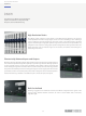
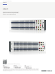
The graphic equaliser shall use centre-detented slide potentiometers with 45 mm travel arranged to give a graphical display of frequency
plotted against level. The slide potentiometers shall have protective covers to inhibit the ingress of dirt and dust.
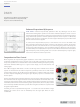
The graphic equaliser shall have one second order (12 dB/oct) high-pass lter per channel with adjustable frequency range 20 Hz to 500 Hz.
The graphic equaliser shall have one second-order (12 dB/oct) low-pass lter per channel with adjustable frequency range 2 kHz to 20 kHz.
The graphic equaliser shall have two notch lters per channel, with overlapping adjustable frequency ranges.
The graphic equaliser low-pass, high-pass and notch lters shall each have a rotary control knob with a latching push switch action and an
illuminating LED ring to indicate the active condition.
The graphic equaliser shall have a channel gain control with range from -∞ to +6 dB per channel.
The graphic equaliser shall have a power-o bypass facility, which shall allow it to return automatically to the bypass condition in the event of
power supply interruption.
The graphic equaliser shall have a recessed front panel power switch designed to avoid accidental operation.
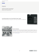
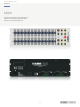
The graphic equaliser shall feature 2 line-level electronically-balanced inputs and 2 line-level electronically-balanced outputs on industry-
standard XLR connectors and Phoenix-style connectors.
The graphic equaliser shall have the option of audio balancing transformers on both the inputs and outputs.
The graphic equaliser shall include an auto-ranging universal switch-mode power supply for use on a worldwide basis.
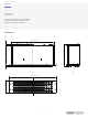
The graphic equaliser shall be housed in a standard 3U 19" rackmount chassis, and shall be 483 mm wide x 228 mm deep x 133 mm high
(19.0" x 9.0" x 5.2"), with nominal weight 5.8 kg (12.8 lbs). The graphic equaliser shall be installed in a rack frame or road case capable of safely
supporting its weight. Input, output, and power connections shall be made at the rear panel of the graphic equaliser. Installers shall allow
adequate space at the rear for connection and disconnection of input, output, and power connections. The power requirements shall be 100 to
240 VAC, 50 to 60 Hz.
The graphic equaliser shall be the KLARK TEKNIK DN370 and no other alternative shall be acceptable.
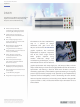
Product Information Document
Dual 30 Band, 1/3 Octave Analogue Graphic
Equaliser with Enhanced Proportional-Q
Response and Four-Band Filtering
Equalizers
DN370