DN530 Creative Quad Gate Operator Manual Klark Teknik, Klark Industrial Park, Walter Nash Road, Kidderminster. Worcestershire. DY11 7HJ. England. Tel: +44 1562 741515 Fax: +44 1562 745371 Email: info@midasklarkteknik.com Website: www.klarkteknik.com DN530 Creative Quad Gate — Operator Manual DOC02-DN530 Issue B — February 2010 © Red Chip Company Ltd. In line with the company’s policy of continual improvement, specifications and function may be subject to change without notice.
IMPORTANT SAFETY INSTRUCTIONS The lightning flash with arrowhead symbol within an equilateral triangle is intended to alert the user to the presence of uninsulated “dangerous voltage” within the product's enclosure that may be of sufficient magnitude to constitute a risk of electric shock to persons. The exclamation point within an equilateral triangle is intended to alert the user to the presence of important operating and maintenance (servicing) instructions in the literature accompanying the product.
INSTRUCTIONS DE SÉCURITÉ IMPORTANTES Le symbole représentant un éclair fléché dans un triangle équilatéral a pour but d'alerter l'utilisateur de la présence d'une "tension dangereuse" non isolée à l'intérieur du boîtier, pouvant être d'une force suffisante pour constituer un risque d'électrocution.
EC-Declaration of Conformity Klark Teknik EC-Declaration of Conformity The undersigned, representing the following manufacturer Manufacturer: Address: Midas Klark Teknik Ltd. Klark Industrial Park, Walter Nash Road, Kidderminster. Worcestershire. DY11 7HJ. hereby declares that the following product Product Type Number Product Description Nominal Voltage(s) Current Freq.
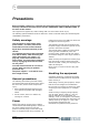
Precautions Before installing, setting up or operating this equipment please ensure that you have read and fully understand all of this section and the “IMPORTANT SAFETY INSTRUCTIONS” at the front of this manual. This equipment is supplied by a mains voltage that can cause electric shock injury! The following special limitations must be observed in order to maintain safety and electromagnetic compatibility performance.
Precautions Installation Radio frequency interference Before installing the equipment: • Power plugs must be inserted in socket outlets provided with protective earth contacts. The electrical supply at the socket outlets must provide appropriate over-current protection. • Both the mains supply and the quality of earthing must be adequate for the equipment. • Before connecting up the equipment, check that the mains power supply voltage rating corresponds with the local mains power supply.
Precautions Safety equipment Optional equipment Never remove, for example, covers, housings or any other safety guards. Do not operate the equipment or any of its parts if safety guards are ineffective or their effectiveness has been reduced. Unless advised otherwise, optional equipment must only be installed by service personnel and in accordance with the appropriate assembly and usage regulations.
Precautions x DN530 Operator Manual
Contents Chapter 1 Introduction . . . . . . . . . . . . . . . . . . . . . . . . . . . . . . . . . 1 Overview of the DN530 Applications . . . . . . . . Features . . . . . . . . . . About this manual . . . Chapter 2 . . . . . . . . . . . . . . . . . . . . . . . . . . . . . . . . . . . . . . . . . . . . . . . . . . . . . . . . . . . . . . . . . . . . . . . . . . . . . . . . . . . . . . . . . . . . . . . . . . . . . . . . . . . . . . . . . . . . . . . . . . . . . . . . . . . .
Contents Sidechain . . . . . . . . . . . . . . Soloing . . . . . . . . . . . . . . . Interfacing with the console . Using gates with compressors Instrument synchronisation . Appendix A . . . . . . . . . . . . . . . . . . . . . . . . . . . . . . . . . . . . . . . . . . . . . . . . . . . . . . . . . . . . . . . . . . . . . . . . . . . . . . . . . . . . . . . . . . . . . . . . . . . . . . . . . . . . . . . . . . . . . . . . . . . . . . . . . . . . . . . . . . . . . . . . . .21 .
Chapter 1: Introduction Thank you for purchasing a Klark Teknik DN530 Creative Quad Gate. The DN530 is a user-friendly, high-performance, four-channel (quad) analogue gate designed for live sound reinforcement with applications in both front-of-house and monitoring situations. Other possible areas for use include broadcasting, the recording studio and installation. The DN530 provides a variety of easy-to-use controls for the precise manipulation of gate parameters.
Chapter 1: Introduction Applications The DN530 provides a quality, cost effective and compact gating unit presented in a traditional 1U quad channel format. This makes it suited to applications where space is limited and is ideal for small touring public address (PA) rigs where the four channels are enough to cover a small drum kit.
Features Features The DN530 has the following features: • The gate action has rock solid triggering. • Advanced band pass sidechain filter, which is easy to set up. • Separate (daisy-chainable) solo bus that allows tuning of the sidechain filter, even during the performance. • Attack is exponential, so that it can be set extremely fast to reduce signal loss at the start of sounds while remaining sonically transparent, that is, with no unwanted clicks.
Chapter 1: Introduction 4 DN530 Operator Manual
Chapter 2: What Is A Gate? The natural sounds of everyday life, which can be caused by anything from, say, the falling of a leaf to the roar of a jet engine, vary extremely widely in sound level. This variance is known as the ‘dynamic range’ and is the difference — expressed in decibels (dB) — between the loudest and quietest sounds in a piece of audio, such as music or speech, or that can be reproduced by a piece of audio equipment without distortion.
Chapter 2: What Is A Gate? Typical creative uses The human ear is connected to an extremely sophisticated organ for processing incoming audio information — the brain. Even in situations where there are many sound sources, we seem to be able to tune in to the sounds we want to hear and reject others. This is sometimes known as the cocktail party effect, where it is possible to pick out one person’s voice — even at a distance — from may conflicting conversations.
Other uses of gating Other uses of gating Gates were originally devised to reduce noise in the silent passages of a music programme, especially during the process of multi-track recording on analogue tape. Although they are still used for reducing noise, many other uses and creative applications have been found for them over the years, including: • Noise reduction. • Removing compressor breathing noise. • Reducing spill from adjacent sound sources. • Gating ambience reverb for effects.
Chapter 2: What Is A Gate? 8 DN530 Operator Manual
Chapter 3: Getting Started Observing the IMPORTANT SAFETY INSTRUCTIONS at the front of the manual and the guidelines in "Precautions" on page vii, carry out the following to get your DN530 unit fully operational. Unpacking Carefully unpack your DN530 equipment package. Then, inspect the DN530 unit carefully for any signs of damage that may have occurred during transit and notify the courier immediately if you discover any. Check the contents of your DN530 equipment package.
Chapter 3: Getting Started Connecting the power cable Making sure that the mains power at the power outlet is off, connect the mains cable supplied with your DN530 to the mains power outlet and then to the mains socket at the rear of your unit. Connecting the audio cables Making sure that all equipment is switched off, connect the DN530 to the rest of your audio equipment as shown in the following subsections. For information on balancing, see “Balanced/unbalanced audio” on page 37.
Connecting the audio cables Sidechain inputs The electronically balanced sidechain inputs are on stereo 1/4” TRS connectors. Inserting a mono jack plug will automatically unbalance the input. The following diagram shows the sidechain input connection details.
Chapter 3: Getting Started Connecting to unbalanced equipment Ideally, you will be making the best use of the DN530’s low-noise high-headroom balanced inputs by connecting to similarly balanced equipment. However, if you do have to connect to unbalanced devices, the following wiring is recommended for best results (see Figure 3): • Connect the +ve (pin 2) of the balanced connection to the +ve terminal on the unbalanced connector.
Chapter 4: Front Panel The front panel of the DN530 has four main channel sections, each containing a number of control knobs, pushbuttons and LEDs. Each main channel section is divided into a gate section and a sidechain section. All of the switches on the front panel are of the latching pushbutton type and have two positions, in and out. Each of these switches have an associated LED above that illuminates to show when the switch is on.
Chapter 4: Front Panel Gate section The gate section houses six gate parameter control knobs, bypass and duck switches, and a set of six metering LEDs. For more information on the gate controls and their uses, see Chapter 6 "Gate Control Functions" on page 19. 9 10 11 1 3 8 2 7 6 5 4 Item Type Label Function 1 Control knob ATTACK Adjusts the time taken for the gate to open after an over-threshold signal.
Gate section Metering The key to successful DN530 operation is to know when signals are above or below threshold. This is especially true if the accent feature is used with low range settings or with no gating action at all. This style of metering provides an intuitive moving LED indication that ramps up and down as the signal level moves around the threshold point. The metering comprises the following LEDs: Label Colour Function CLIP Red Clip LED for showing when the signal is being clipped.
Chapter 4: Front Panel Sidechain section The signals that feed the gate’s sidechain are called the "sidechain". A band pass filter is provided that acts on the sidechain signals. The sidechain section for each channel can be broadly divided into two areas: filter and solo. The filter section comprises the FREQUENCY control knob and the FILTER and EXT pushbuttons, and the solo section consists of the SOLO pushbutton.
Chapter 5: Rear Panel The rear panel of the DN530 (shown below) has three main connector sections: mains input, solo bus and the four channels. Mains input Solo bus Four channels Mains input The mains input section has a mains IEC socket, below which is a fuse drawer. Printed to the right are mains supply voltage and fuse details. Mains IEC socket The mains input is an auto-voltage sensing switch mode power supply that operates where normal mains voltage is in the range 100V AC to 240V AC.
Chapter 5: Rear Panel Solo bus The solo bus section comprises an input and an output XLR chassis connector. These are connected to an external monitor input, such as a mixing console, or they can be daisy-chained to other units being monitored (see Figure 3, “Daisy-chaining the DN530s (solo bus),” on page 23).
Chapter 6: Gate Control Functions This chapter gives details of the control functions of the DN530 gate. Attack Attack is the time taken for the gate to open after an over threshold signal. The shape of the attack is fixed and has been carefully tailored to produce a transparent gating action. Hold Minimises chattering in conjunction with the internal hysteresis. Once the signal has been detected as having fallen below threshold, this control defines a waiting period before the gate starts to close.
Chapter 6: Gate Control Functions The advantage of generating the effect in this way is that it is much more straightforward to set up and has the added benefit that the attack control operates to change the sonic character of the accent as well as the gate. This allows a more precise tailoring of the sound produced — changing from tight and snappy to more of a low-end thud as you increase the attack time.
Chapter 7: Using The Gate The DN530 is a gate processor that utilises premium quality, high precision components to achieve a high degree of accuracy and control. The DN530 has been designed primarily for creative use as front of house (FOH) or monitor. However, it is just as effective when used in the studio while broadcasting or recording. The DN530 processors offer, in a compact unit, control over the dynamic range for creative and corrective purposes.
Chapter 7: Using The Gate External sidechain input (1/4” TRS jack) Input (female XLR connector) DN530 (rear panel) Output (male XLR connector) Channel insert point (contact mic) Snare Mic Mic inputs Return Contact mic (snare mic) Send Send (snare mic) Console Figure 2: Typical set up for external sidechain operation 22 DN530 Operator Manual
Soloing Soloing You can monitor the sidechain during the performance using the dedicated solo output. To do this, connect the solo output to a spare input channel, line return, effects return etc., on your mixing console. Enabling any solo pushbutton will route that processor’s sidechain monitor to the solo output, allowing monitoring of the sidechain filter without interrupting the audio output of the processor. The rear panel of the DN530 includes a solo bus with input and output XLRs.
Chapter 7: Using The Gate Interfacing with the console The DN530 is optimised for use at line level, therefore to gate a mic, the input to the DN530 has to be taken from the console, preferably from the channel insert point send. The output from the DN530 comes back to the channel insert return. By connecting the DN530 at this position in the signal chain, its operation is unaffected by the use of any of the console controls, except input gain.
Using gates with compressors Using gates with compressors One of the most important applications of a noise gate is the reduction of noise emphasised by the action of compressors. When any signal is compressed, the highest levels are reduced, but the lowest noise levels remain the same. This effectively decreases the signal to noise ratio.
Chapter 7: Using The Gate Instrument synchronisation Sometimes it is necessary to synchronise the attack of two instruments. Often a bass guitar must be made to synchronise precisely to the regular beat of the bass drum. This can be done by passing the bass guitar through the gate and using the bass drum as the external sidechain.
Appendix A: Application Notes As most dynamics processing is a matter of personal taste and preference, these application notes are provided as a guide only. Experimenting in unconventional areas can often yield interesting and useful results. Always remember, be creative with your DN530 — and have fun! When using noise gates, try experimenting with the attenuation depth for more subtle gating.
Application Notes If the gate is being used creatively, the effect of the gate opening transition can be accentuated. This is particularly useful on drums, improving definition and punch. The accent effect is totally independent of the range control, so it is possible to reduce the range very low or even off (0dB) and still achieve a noticeable enhancement of transients.
Envelope shaping Envelope shaping A rhythmic pulse of 8th or 16th notes going all the way through a song is a common musical device. This could be a sequenced synthesiser, but a more interesting method is possible using the DN530. The synthesiser is set up to provide continuous sustained notes (changing according to the harmony of the song), perhaps being processed by a chorus unit before passing through the gate. A drum machine or sequencer is programmed to produce a regular chain of 8th or 16th notes.
Application Notes Chatter Chatter can normally be eliminated by increasing the hold time, but this may allow the gate to stay open longer than is desirable. Adding hysteresis to the threshold control helps enormously and allows hold times to be reduced without signal chatter. The DN530 has 4dB of i-TS hysteresis built in, which is enough to eliminate chatter on all normal instrument types.
Noise enhancement Noise enhancement We all have the ability to block out constant background noises and often using a gate to eliminate background noises altogether defeats this mechanism. This tends to draw our attention to the noise when the gate opens. Typically, adjusting the gate range down to 10dB or 15dB produces results that sound much more natural. Ducking Ducking is used to automatically reduce the signal levels when the level of a source signal (from the external sidechain) goes over threshold.
Application Notes 32 DN530 Operator Manual
Appendix B: Technical Specification This appendix contains the technical specifications specific to the DN530.
Technical Specification Gate Threshold Range Attack Release Hold Accent Scale Scale Scale Scale Scale Scale Filter Sidechain filter Scale = 40Hz to 16kHz Terminations Audio Power 3-pin XLRs (male and female) and 1/4” TRS balanced jack sockets 3-pin IEC Power requirements Voltage Frequency Consumption 100VAC to 240VAC ±10% 50Hz to 60Hz <25W Dimensions Height Width Depth 44.5 mm (1.75”), 1U high 483 mm (19”) 305 mm (12”) Weight Net Shipping 4.6 kg 5.
Appendix C: Functional Block Diagram The following page contains the signal flow diagram for the DN530.
IN 1 36 PUSH SOLO BUS IN EXTERNAL SIDECHAIN 1 PUSH _ + _ + _ + EXT Peak Detector SIDECHAIN 1 From Channels 2-4 SOLO 25 0dB THRESHOLD -50 FILTER 16k 40Hz FREQUENCY -20 800 200 2s 2s 2ms HOLD 0.3 0.03 Envelope control RELEASE 10ms 2ms 30us ATTACK 0.3 0.
Appendix D: Balanced/Unbalanced Audio Balancing refers to the type of input or output signal connections in an audio system. These connections are specifically designed to reject external noise, such as from mains wiring and internal interference from adjacent signal cables.
Balanced/Unbalanced Audio 38 DN530 Operator Manual
Appendix E: Crib Sheet The following page contains a crib sheet. You can photocopy (or print) this page if you want more copies.
40 QUAD GATE CREATIVE DN530 QUAD GATE CREATIVE DN530 QUAD GATE CREATIVE DN530 BYPASS SOLO 200 EXT 800 BYPASS SOLO 200 EXT 800 DUCK SHUT REL 0dB RANGE 10 25 BYPASS DUCK 12 ACCENT 8 2ms HOLD 2s 0.3 2s 0.3 RELEASE 0.03 10ms 2ms ATTACK 0dB 4 30us 0.03 2s SOLO 200 EXT 800 SIDECHAIN 1 16k FILTER 40Hz FREQUENCY 16k FILTER 40Hz FREQUENCY SHUT REL HLD 40 12 8 ACCENT 0dB 4 DUCK BYPASS 2s 0.3 12 ACCENT 8 2ms HOLD 0.
Appendix F: Service Information This appendix contains routine service and maintenance instructions. Routine maintenance To help keep your DN530 unit in good working order and to make sure it gives you optimum performance, we recommend that you carry out the following at monthly intervals: • Clean the unit (see “Cleaning” below). • Check the controls for freedom of operation. • Check the functionality of all controls, that is, control knobs, pushbuttons and LEDs.
Service Information Equipment disposal When this equipment has come to the end of its useful life, its disposal may come under the DIRECTIVE 2002/96/EC OF THE EUROPEAN PARLIAMENT AND OF THE COUNCIL of 27 January 2003 on waste electrical and electronic equipment (WEEE). Hazardous substances in WEEE contaminate water, soil and air and ultimately put at risk our environment and health. The directive aims to minimize the impacts of WEEE on the environment during their life times and when they become waste.
Thank you for reading through this Operator Manual. We hope you found it useful. Please feel free to send us your comments. Our contact details and website address can be found at the front of this manual.
© 2011 Red Chip Company Ltd. Klark Teknik Klark Industrial Park, Walter Nash Road, Kidderminster. Worcestershire. DY11 7HJ. England. Tel: +44 1562 741515, Fax: +44 1562 745371 Email: info@midasklarkteknik.com Website: www.klarkteknik.