
Use and Care Manual


6
ENGLISH
6
OPERATING INSTRUCTIONS
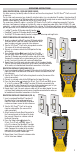
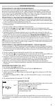
TESTING CONTINUITY ON TERMINATED OR INSTALLED RJ45/RJ11/RJ12 CABLE (FIG. 1, FIG. 2):
1. Connect one end of the cable under test to the RJ45 port (if testing a data cable) or RJ11/RJ12 port (if testing
a voice cable) located at the top of the main tester body. If testing a wall port, connect a known good patch
cable from the wall plate to the appropriate port at the top of the main tester body.
2. Connect the other end of the cable under test to the corresponding port on the testing remote. If testing a
wall port, connect a known good patch cable from the wall port to the appropriate port on the testing remote.
NOTE: Location-only ID remotes cannot be used.
3. Press the Data button
C
or the Voice button
A
on the keypad to begin the test.
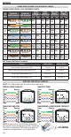
4. Interpret the results of the test using the WIRING AND DISPLAY EXAMPLES section.
TESTING CONTINUITY ON TERMINATED OR INSTALLED COAX CABLE (FIG. 3, FIG. 4):
1. Attach female-to-female Barrel Connector to the F-connector port on the top of the tester.
2. Connect one end of the cable to be tested to this adapter.
3. If testing a terminated coax cable, attach a second Barrel Connector to the other end of the cable under test.
NOTE: This step is not necessary if testing an installed coax cable, or a cable attached to a wall plate.
4. Connect either a numbered CoaxMap™ Location ID Remote or one of the Test + Map™ ID Remotes to the
Barrel Connector.
5. Press the Video button
B
to begin the test.
6. Interpret the results of the test using the WIRING AND DISPLAY EXAMPLES section.
-OR-
-OR- -OR-
-OR-
FIG. 1 FIG. 2
FIG. 4FIG. 3
-OR- -OR-
-OR- -OR-