
Use and Care Manual


4
ENGLISH
OPERATING INSTRUCTIONS
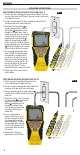
LENGTH MEASUREMENT: The VDV Scout
TM
Pro 3 uses the capacitive properties of a cable to measure its
length. One end of the cable should be connected to the corresponding port on the top of the tester. The other
end should be left disconnected or attached to the self-storing remote.
LENGTH CONSTANT:
The length constant refers to the electrical characteristic of a cable used to characterize
length. Every cable has an associated length constant in units of picofarads per foot (pf/ft.). Setting the length
constant on the tester is important to obtaining an accurate cable length measurement from the VDV Scout
TM
Pro 3.
The default length constants are as follows: Voice: 17.0pF/ft. Data: 15.0pF/ft. Video: 15.0pF/ft.
The length constant can sometimes be provided by the manufacturer of the cable (see DISPLAYING/EDITING LENGTH
CONSTANT section). You may have to determine the length constant yourself (see DETERMINING AN UNKNOWN
LENGTH CONSTANT section). Length constants can range from 10pF/ft. to 40pF/ft.
Measurement accuracy is dependent on how close the tester can be set to the length constant of the cable being
measured and the consistency of the cable along its length.
The length constant can vary from cable to cable, even of the same type produced by the same manufacturer. It can also
vary over the length of one cable because the length constant is dependent on the physical properties of the cable, which
may not be consistent throughout the entire cable. The change in wire pair spacing through the cable can vary the length
constant along the length of the cable.
When setting the length constant using a length of cable, the cable should be at least 50 ft. long. This will yield a ±5%
uncertainty (1 in 50) of length constant accuracy. A longer cable reduces this uncertainty.
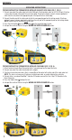
MEASURING LENGTH – VOICE OR DATA CABLES:
1. Press the Power button
G
to turn tester on.
2. Connect one end of the cable to the appropriate port: RJ45 port
(if testing data cable), RJ12 port (if testing voice cable), located at the top
of the main tester body. Leave the other end of the cable unterminated.
3. Press the Length button
F
to enter Length mode.
4. Press the Data button
C
or Voice button
A
,
depending on the cable being tested, to begin the test.
5. Press the Data button
C
repeatedly to select the pair of wires that
should be measured. The first functional pair is chosen by default.
6. Read the length measurement as shown
.
MEASURING LENGTH – COAX CABLES:
1. Press the Power button
G
to turn tester on.
2. Connect one end of the cable to the F-connector port
located at the top of the main tester body.
Leave the other end of the cable unterminated.
3. Press the Length button
F
to enter Length mode.
4. Press the Video button
B
to begin the test.
5. Read the length measurement as shown
.
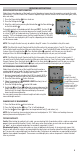
DISPLAY
• MODE: The top line of the display shows what cable
type is being tested; voice (RJ11/RJ12)
1
, video
(F-terminated coax)
3
or data (RJ45)
5
, and if
HubBlink mode
4
or Tone mode
2
is activated.
• PASS/SPECIAL CABLES: “Pass”
6
will be displayed
if the cable is a properly wired 4-pair T568A/B data
cable, a 3-pair one-to- one wired voice cable or a
video cable with no faults. In addition, “X-over”
7
illuminates if a properly wired cross-over (uplink)
cable is recognized, or “Rev”
8
illuminates if the
cable is a properly wired reverse-pinned voice cable.
The wire map will show actual pin connections.
“Shielded”
9
illuminates when a shielded data cable
is properly connected at both ends. It will be flashing
if there is a short to a wire in the cable along with that
pin number and the “Short”
11
indicator.
• CABLE FAULTS: “Fail”
10
will illuminate only if the cable is not wired to one of the cabling standards. "Short" (two
wires making conductive contact)
11
, "Split" (wire pairs not maintained as pairs when terminated)
12
, "Open" (wires
not making connection at both ends of the cable)
13
, or a combination of these will also illuminate to indicate the
type of fault(s) detected. SeeWIRING AND DISPLAY EXAMPLES section for wire standards and failure modes.
• VOLTAGE CHECK: A check for voltage on the RJ45 terminated data cable is performed before each test and if
found, no test is run. If voltage is detected on any of the tester connectors, the lightning bolt icon
14
illuminates. The tester should be disconnected immediately from the source of the voltage.
• MEASUREMENT:
15
Length mode: Length of cable run in feet or meters. PoE mode: Voltage.
• LOCATION ID:
16
The remote ID number will display here.
• BATTERY STATUS: The battery low icon
17
illuminates when the battery is nearing depletion. The icon will
illuminate when the battery needs to be replaced. Results may be unreliable at this point.
• TESTER-END WIRE MAP:
18
Displays the pins on the tester end of the cable in order. These pins are mapped
to the pins on the remote-end shown directly below them on the LCD
• REMOTE-END WIRE MAP:
19
Displays the corresponding pin on the remote-end. Dashed lines on this row
indicate shorted pins. No pin numbers displayed on this row line are open pairs.
• PoE INDICATORS:
20
Indicate PoE configuration. See chart on page 10 for details.
• PoE ERROR INDICATOR:
21
Indicates no PoE detected when test is initiated.
Cable
Type
Indicates
Shielded
cable
Remote ID#
(if terminated)
Measured Length = 45 ft.
Test Running
Continuously
NOTE: A voice or data cable under test can be
unterminated (open) or terminated by an RJ45
ID remote. If it is terminated by the self-storing
remote, the reading will be 1 to 2 ft. greater than
the actual measurement. In this case, subtract
1 to 2 ft. from the reading to obtain the actual
measurement. Coax cable under test maybe left
unterminated.
1 2
3
4
5 6
7
8
ID
Pass X-over Rev
Fail Short
Split Open
Shielded
PoE
ft
m
+
B
A
3 4 51
10
11 11
6
18
19
14
17
21
7 8 92
15
16
12
20