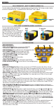
VDV ScoutTM Pro 3 ENGLISH VDV501-852 VDV501-853 pg. 2 INSTRUCTION MANUAL • VOICE, DATA AND VIDEO CABLE TESTING • DETECTS SHORT FAULTS, OPEN FAULTS, REVERSALS, MISWIRES, CROSSOVER WIRING AND SPLIT PAIRS • POWER OVER ETHERNET (PoE) • CABLE ID • LENGTH MEASUREMENT • TONE GENERATOR • EXTRA-LARGE BACKLIT LCD • HUB BLINK • AUTO POWER-OFF DEUTSCH Pass X-over Rev Shielded A Fail Short Split OpenPoE+ B pg.
ENGLISH GENERAL SPECIFICATIONS The Klein Tools VDV ScoutTM Pro 3 is a portable voice-data-video cable tester. It tests and troubleshoots RJ11, RJ12, RJ45 and F-connector terminated cables, and provides tone generation for cable tracing. The VDV ScoutTM Pro 3 also measures cable length, tests for shield, performs hub blink testing and traces up to 19 locations (up to 5 locations with the included remotes, additional remotes are available separately). • • • • • • Dimensions: 6.5" x 3.0" x 1.6" (16.5 x 7.
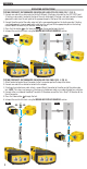
ENGLISH SELF-STORING TEST + MAP™ ID REMOTE (VDV501-210) Use for cable location identification mapping and/or continuity testing. Self-storing remotes display on tester as Remote ID No. 1. Included with all VDV ScoutTM Pro 3 models. RJ11/12 port F-connector port RJ45 port TEST + MAP™ ID REMOTES (VDV501-2## SERIES) Use for cable location identification mapping and continuity testing. Remotes display on tester as Remote ID Nos. 1-12. Set Nos. 2–6 included with VDV500-853 and sold separately, set Nos.
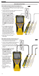
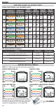
ENGLISH DISPLAY 1 11 2 7 3 8 13 4 9 5 • MODE: The top line of the display shows what cable type is being tested; voice (RJ11/RJ12) 1 , video (F-terminated coax) 3 or data (RJ45) 5 , and if Hub Blink mode 4 or Tone mode 2 is activated. • PASS/SPECIAL CABLES: 'Pass' 6 will be displayed 6 Pass X-over Rev Shielded 20 if the cable is a properly wired 4-pair T568A/B data A 10 Fail Short Split OpenPoE+ B 16 cable, a 3-pair one-to-one wired voice cable or a 12 video cable with no faults.
OPERATING INSTRUCTIONS DISPLAYING/EDITING LENGTH CONSTANT: Follow these instructions to set the length constant based on a known value (for example, as given by the cable manufacturer). The VDV ScoutTM Pro 3 stores a separate length constant for each of the three cable types (voice, data and video). 1. Press the Power button G to turn the tester on. 2. Press the Settings button E . Cable Type 3. Select the cable type by pressing the Voice button A , the Coax button B or the Data button C .
ENGLISH OPERATING INSTRUCTIONS TESTING CONTINUITY ON TERMINATED OR INSTALLED RJ45/RJ11/RJ12 CABLE (FIG. 1, FIG. 2): 1. Connect one end of the cable under test to the RJ45 port (if testing a data cable) or the RJ11/RJ12 port (if testing a voice cable), located at the top of the main tester body. If testing a wall port, connect a known good patch cable from the wall plate to the appropriate port at the top of the main tester body. 2.
OPERATING INSTRUCTIONS CABLE IDENTIFICATION – DATA AND VOICE CABLES: It is often necessary to identify cables that branch out from the wiring closet. The VDV ScoutTM Pro 3 can assist in two ways: The first and most convenient way to identify installed cables is by using location ID remotes. Using location ID remotes, you can trace up to 19 drop locations with one trip to the wiring closet or router. Identification with ID remotes is done digitally and does not rely on any manual tracing.
ENGLISH OPERATING INSTRUCTIONS TONE TRACING ON INSTALLED RJ45/RJ11/RJ12 CABLE (FIG. 7): 1. Connect a known working patch cable to the RJ45 port (if you are tracing a Data cable) or RJ12 port (if you are tracing a voice cable) at the top of the tester. FIG. 7 2. Connect the other end of the patch cable to the wall port at the satellite location of the cable under test. 3. Short press the Tone button D to initialise the tone generation.
OPERATING INSTRUCTIONS TESTING CONTINUITY & CABLE IDENTIFICATION SIMULTANEOUSLY: The VDV ScoutTM Pro 3 has the capability of simultaneously testing continuity and providing cable location identification for up to twelve locations with Test + Map™ ID Remotes (sold separately). The VDV ScoutTM Pro 3 series testers come with the Self-Storing Test + Map™ ID Remote No. 1. Test + Map™ ID Remotes No. 2 through No. 6 are included in some kits (VDV501-853, VDV770-850), Test + Map™ ID Remotes No. 7 through No.
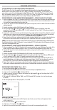
ENGLISH POWER OVER ETHERNET (PoE) REFERENCE CHARTS POWER OVER ETHERNET (PoE) REFERENCE CHARTS 10/100 10/100 1000 (1 GB) Pin Mode B Mode A Mode B TIA/EIA-568 TIA/EIA-568 at T568B Termination T568A Termination DC on Spares Mixed DC & Data DC & Bi-Data Source Data Power Data Power Data Power 1 2 3 4 5 6 7 8 White/Orange White/Green Orange Verde White/Green White/Orange Blue Blue White/Blue White/Blue Green Orange White/Brown White/Brown Brown Brown 1000 (1 GB) Mode A DC & Bi-Data Data Power
WIRE MAP AND DISPLAY EXAMPLES COAX CABLE PROPERLY WIRED: COAX CABLE WITH AN OPEN: COAX CABLE WITH A SHORT: NOTE: An open fault will also occur when no remote is connected to the satellite end of a video/coax cable. Pass Open ID Short BATTERY REPLACEMENT 1. Loosen screw ion battery cover with No. 2 Phillips screwdriver. 2. Remove the battery door. 3. Disconnect the battery cable and recycle the exhausted battery. 4. Install a fresh 9-volt alkaline battery. 5.
DEUTSCH ALLGEMEINE TECHNISCHE DATEN Der Klein Tools VDV Scout Pro 3 ist ein tragbarer Kabeltester für Sprach-, Daten- und Videokabel. Er dient zur Prüfung und Fehlersuche bei Kabeln mit RJ11-, RJ12-, RJ45- und F-Steckern und verfügt über einen Tongenerator zur leichten Kabelverfolgung.
DEUTSCH SELBSTVERSTAUENDE TEST-N-MAP™ REMOTE-ORTUNGSEINHEIT (VDV501-210) Ortung, Identifizierung und Zuordnung von Leitungen und/oder Durchgangsprüfungen. Die selbstverstauenden Remote-Einheiten werden auf dem Prüfer-Display als Remote ID Nr. 1 angezeigt. Stets im Lieferumfang von VDV ScoutTM Pro 3 Modellen enthalten. RJ11/12Buchse F-Buchse RJ45Buchse TEST-N-MAP™ REMOTE-ORTUNGSEINHEITEN (VDV501-2XX-SERIE) Ortung, Identifizierung und Zuordnung von Leitungen und Durchgangsprüfungen.
DEUTSCH DISPLAY 1 11 2 7 3 8 13 4 9 5 • MODUS: Die obere Zeile des Displays zeigt an, welcher Kabeltyp getestet wird – Sprach- (RJ11/RJ12) 1 , Video(Koaxialkabel mit F-Buchse) 3 oder Datenkabel (RJ45) 5 – und ob der Hub-Blink- 4 oder Tonmodus 2 aktiviert ist.
BETRIEBSANLEITUNG MESSUNG DER LÄNGE – KOAXIALKABEL: 1. Drücken Sie die Einschalttaste G , um den Tester einzuschalten. 2. Verbinden Sie ein Kabelende mit der F-Buchse an der Oberseite des Prüfgeräts. Lassen Sie das andere Kabelende frei. 3. Drücken Sie die Längentaste F , um den Modus Längenmessung aufzurufen. 4. Drücken Sie die Videotaste B zum Starten des Tests. Lesen Sie den angezeigten Längenmesswert ab.
DEUTSCH BETRIEBSANLEITUNG DURCHGANGSPRÜFUNG BEI ABGESCHLOSSENEM ODER VERLEGTEM RJ45-/RJ11-/RJ12-KABEL (ABB. 1, ABB. 2): 1. Verbinden Sie ein Ende des zu prüfenden Kabels mit der RJ45-Buchse (falls Sie ein Datenkabel prüfen) oder der RJ11/ RJ12-Buchse (falls Sie ein Sprachkabel prüfen) an der Oberseite des Prüfgeräts. Um eine Wandbuchse zu überprüfen, verbinden Sie ein bekanntermaßen funktionierendes Patchkabel von der Wandplatte mit der entsprechenden Buchse an der Oberseite des Prüfgeräts. 2.
BETRIEBSANLEITUNG KABELIDENTIFIZIERUNG – DATEN- UND SPRACHKABEL Eine typische Ortungsaufgabe ist die Erkennung von Kabeln, die von einem Verteilerschrank abgehen. Das Prüfgerät VDV ScoutTM Pro 3 kann Sie dabei auf zweierlei Weise unterstützen: Die erste – und einfachste – Möglichkeit ist die Identifizierung verlegter Kabel mithilfe von Remote-Ortungseinheiten. Mit Remote-Ortungseinheiten können Sie mit nur einem Gang zum Verteilerschrank oder Router bis zu 19 Drop-Locations identifizieren.
DEUTSCH BETRIEBSANLEITUNG TONORTUNG BEI VERLEGTEM RJ45-/RJ11-/RJ12-KABEL (ABB. 7): 1. Verbinden Sie ein bekanntermaßen funktionierendes Patchkabel mit der RJ45-Buchse (falls Sie ein Datenkabel verfolgen) oder der RJ12-Buchse (falls Sie ein Sprachkabel verfolgen) an der Oberseite des Prüfgeräts. ABB. 7 2. Verbinden Sie das andere Ende des Patchkabels mit der Wandbuchse am anderen Ende des zu prüfenden Kabels. 3. Drücken Sie die Tontaste D kurz, um die Tonausgabe zu aktivieren.
BETRIEBSANLEITUNG GLEICHZEITIGE DURCHGANGSPRÜFUNG UND KABELIDENTIFIZIERUNG: In Verbindung mit den Test-n-Map™ Remote-Ortungseinheiten (separat erhältlich) bietet das Prüfgerät VDV ScoutTM Pro 3 die Möglichkeit, für bis zu zwölf Kabelstandorte gleichzeitig eine Durchgangsprüfung und die Kabelortung durchzuführen. Die Prüfgeräte der Reihe VDV ScoutTM Pro 3 werden mit der selbstverstauenden Test-n-Map™ Remote-Ortungseinheit Nr. 1 geliefert. Die Test-n-Map™ Standard-Remote-Ortungseinheiten Nr.
DEUTSCH POWER OVER ETHERNET (PoE) REFERENZTABELLEN POWER OVER ETHERNET (PoE) REFERENZTABELLEN Stift an Quelle 1 2 3 4 5 6 7 8 TIA/EIA-568 T568BKontaktierung TIA/EIA-568 T568AKontaktierung Weiß/orange Weiß/grün Orange Grün Weiß/grün Weiß/orange Blau Blau Weiß/blau Weiß/blau Grün Orange Weiß/braun Weiß/braun Braun Braun 10/100 Modus B DC auf ungenutzten Leitungen 10/100 Modus A DC und Daten kombiniert 1000 (1 GB) 1000 (1 GB) Modus B Modus A DC und DC und bidirektionale Daten bidirektiona
VERKABELUNGSPLAN UND DISPLAY-ANZEIGEN – BEISPIELE KORREKT VERDRAHTETES KOAXIALKABEL: KOAXIALKABEL MIT UNTERBRECHUNG: Pass Open ID KOAXIALKABEL MIT KURZSCHLUSS: HINWEIS: Eine Leitungsunterbrechung („open“-Fehler) kann auch auftreten, wenn keine RemoteEinheit mit dem Satellitenende eines Video-/Koaxialkabels verbunden ist. Short BATTERIEWECHSEL Lösen Sie die Schraube an der Batterieabdeckung mit einem Phillips-Kreuzschlitz Nr. 2. Entfernen Sie die Batterieabdeckung.
FRANÇAIS CARACTÉRISTIQUES GÉNÉRALES L'appareil Klein Tools VDV Scout Pro 3 est un testeur de câbles audio, vidéo et de données portable. Il teste et dépanne les câbles terminés par une fiche RJ11, RJ12, RJ45 et par un connecteur F et comporte un générateur de tonalité pour le repérage des câbles.
FRANÇAIS TÉLÉCOMMANDE D'IDENTIFICATION TEST + MAP™ EMBOÎTABLE (VDV501-210) Utiliser pour le mappage d'identification de localisation et/ou les tests de continuité de câbles. Les télécommandes emboîtables s'affichent sur le testeur sous la forme Remote ID #1. Fournies avec tous les modèles VDV ScoutTM Pro 3.
FRANÇAIS ÉCRAN • MODE : La ligne supérieure de l'écran indique le type de 1 11 2 7 3 8 13 4 9 5 câble testé : téléphonique (RJ11/RJ12) 1 , vidéo (coaxial terminé par connecteur F) 3 ou données (RJ45) 5 , et si le mode Hub Blink 4 ou le mode Tonalité 2 est activé.
INSTRUCTIONS D’UTILISATION AFFICHAGE/MODIFICATION DE LA CONSTANTE DE LONGUEUR : Suivre les instructions ci-dessous pour définir la constante de longueur en fonction d'une valeur connue (par exemple, fournie par le fabricant du câble). Le VDV ScoutTM Pro 3 mémorise une constante de longueur distincte pour chacun des trois types de câble (téléphonique, données et vidéo). 1. Appuyer sur la touche Marche/Arrêt G pour mettre le testeur sous tension. 2. Appuyer sur le bouton Paramètres E . 3.
FRANÇAIS INSTRUCTIONS D’UTILISATION TEST DE CONTINUITÉ SUR CÂBLES RJ45/RJ11/RJ12 TERMINÉS OU INSTALLÉS (FIG. 1, FIG. 2) : 1. Connecter une extrémité du câble à tester au port RJ45 (pour un câble de données) ou au port RJ11/RJ12 (pour un câble téléphonique). Ces ports sont situés à la partie supérieure du corps principal du testeur.
INSTRUCTIONS D’UTILISATION IDENTIFICATION DES CÂBLES - CÂBLES DE DONNÉES ET TÉLÉPHONIQUE : Il est souvent nécessaire d'identifier des câbles qui sortent de l'armoire de câblage. Le VDV ScoutTM Pro 3 peut y contribuer de deux façons : Le premier moyen, qui est aussi le plus pratique, d'identifier des câbles installés consiste à utiliser des télécommandes d'identification de localisation.
FRANÇAIS INSTRUCTIONS D’UTILISATION REPÉRAGE PAR TONALITÉ SUR UN CÂBLE RJ45/RJ11/RJ12 INSTALLÉ (FIG. 7) : 1. Connecter un câble de raccordement réputé satisfaisant au port RJ45 (pour repérer un câble de données) ou au port RJ12 (pour repérer un câble de téléphone). Ces ports sont situés à la partie supérieure du testeur. FIG. 7 2. Connecter l'autre extrémité du câble de raccordement au port mural à l'emplacement satellite du câble testé. 3.
INSTRUCTIONS D’UTILISATION TEST SIMULTANÉ DE CONTINUITÉ ET D'IDENTIFICATION DE CÂBLES : Le VDV ScoutTM Pro 3 a la capacité de tester simultanément la continuité et de fournir l'identification de localisation de câbles en détectant jusqu'à douze emplacements avec des télécommandes d'identification de localisation Test + Map™ (vendues séparément). Les testeurs de la série VDV ScoutTM Pro 3 sont livrés avec la télécommande d'identification Test + Map™ emboîtable n° 1.
FRANÇAIS POWER OVER ETHERNET (PoE) - TABLEAUX DE RÉFÉRENCE POWER OVER ETHERNET (PoE) - TABLEAUX DE RÉFÉRENCE Broche Terminaison TIA/ source EIA-568 T568B Terminaison TIA/ EIA-568 T568A 10/100 Mode B CC sur fils inutilisés Données Alim.
EXEMPLES DE BROCHAGE ET D'AFFICHAGE CÂBLE COAXIAL CORRECTEMENT CÂBLÉ : CÂBLE COAXIAL COMPORTANT UN CIRCUIT OUVERT : Pass Open ID CÂBLE COAXIAL COMPORTANT UN COURT-CIRCUIT : REMARQUE : Un défaut de type circuit ouvert se produit également lorsqu'aucune télécommande n'est connectée à l'extrémité satellite d'un câble vidéo/ coaxial. Short REMPLACEMENT DE LA PILE 1. 2. 3. 4. 5. 6. Desserrer la vis du couvercle du logement de la pile avec un tournevis cruciforme n° 2.
ESPAÑOL ESPECIFICACIONES GENERALES El comprobador VDV Scout Pro 3 de Klein Tools es un comprobador portátil de cables de voz, datos y vídeo. Comprueba y localiza problemas en cables con terminales RJ11, RJ12, RJ45 y conectores F, y permite generar tonos para su localización.
ESPAÑOL CONTROL REMOTO DE ID CON AUTOALMACENAMIENTO TEST + MAP™ (VDV501-210) Se utiliza para la identificación de la ubicación de los cables y/o para pruebas de continuidad. Los controles remotos con autoalmacenamiento se muestran en el comprobador con la ID remota n.o 1. Se incluye con todos los modelos VDV ScoutTM Pro 3.
ESPAÑOL PANTALLA • MODO: La línea superior de la pantalla muestra el tipo de cable 1 11 2 7 3 8 13 4 9 5 que se está probando: voz (RJ11/RJ12) 1 , vídeo (coaxial con terminal F) 3 o datos (RJ45) 5 ; e indica si está activado el modo de parpadeo en el hub 4 o el de tono 2 .
INSTRUCCIONES DE USO MOSTRAR / EDITAR LA CONSTNATE DE LONGITUD: Siga estas instrucciones para establecer la constante de longitud en base a un valor conocido (por ejemplo, el indicado por el fabricante del cable). El VDV ScoutTM Pro 3 almacena una constante de longitud separada para cada uno de los tres tipos de cable (voz, datos y vídeo). 1. Pulse el botón de encendido G para encender el comprobador. 2. Pulse el botón de ajustes E . 3.
ESPAÑOL INSTRUCCIONES DE USO PRUEBA DE CONTINUIDAD EN UN CABLE CON TERMINAL RJ45 / RJ11 / RJ12 O INSTALADO (FIG. 1, FIG. 2): 1. Conecte un extremo del cable que se va a probar al puerto RJ45 (si se está comprobando un cable Ethernet) o al puerto RJ11 / RJ12 (si se está comprobando un cable de voz) situado en la parte superior del cuerpo principal del comprobador.
INSTRUCCIONES DE USO IDENTIFICACIÓN DE CABLES DE VOZ Y DATOS: A menudo es necesario identificar los cables que salen de un armario de cableado. El VDV ScoutTM Pro 3 puede ayudar de dos maneras: La forma más cómoda y sencilla de identificar los cables instalados es utilizar controles remotos de identificación de ubicación. Si se utilizan controles remotos de identificación de ubicación, se pueden analizar hasta 19 tramos de cableado con un solo desplazamiento al router o al armario de cableado.
ESPAÑOL INSTRUCCIONES DE USO ANÁLISIS DE TONOS EN UN CABLE CON TERMINAL RJ45 / RJ11 / RJ12 INSTALADO (FIG. 7): 1. Conecte un cable de fiabilidad conocida al puerto RJ45 (si se está comprobando un cable de datos) o al puerto RJ12 (si se está comprobando un cable de voz) de la parte superior del comprobador. FIG. 7 2. Conecte el otro extremo del cable de conexión a la toma de la pared en la ubicación satélite del cable sometido a comprobación. 3.
INSTRUCCIONES DE USO COMPROBACIÓN DE LA CONTINUIDAD E IDENTIFICACIÓN DE CABLES SIMULTÁNEAMENTE: El VDV ScoutTM Pro 3 puede comprobar la continuidad e identificar hasta doce ubicaciones de cable simultáneamente con los controles remotos de ID Test + Map™ (que se pueden adquirir por separado). Los comprobadores de la serie VDV ScoutTM Pro 3 incluyen el control remoto con autoalmacenamiento Test + Map™ con ID n.º 1. Los controles remotos de ID Test + Map™ n.
ESPAÑOL TABLAS DE REFERENCIA PARA LA ALIMENTACIÓN A TRAVÉS DE ETHERNET (PoE) TABLAS DE REFERENCIA PARA LA ALIMENTACIÓN A TRAVÉS DE ETHERNET (PoE) Pin TIA/EIA-568 TIA/EIA-568 en la Terminación T568B Terminación T568A fuente 1 2 3 4 5 6 7 8 Blanco / Naranja Blanco / Verde Naranja Verde Blanco / Verde Blanco / Naranja Azul Azul Blanco / Azul Blanco / Azul Verde Naranja Blanco / Marrón Blanco / Marrón Marrón Marrón 10/100 Modo B CC en libres 10/100 Modo A Mezcla CC y datos 1000 (1 GB) Modo B
EJEMPLOS DE CABLEADO Y VISUALIZACIÓN CABLE COAXIAL CORRECTAMENTE CABLEADO: CABLE COAXIAL CON UNA ABERTURA: Pass Open ID CABLE COAXIAL CON UN CORTOCIRCUITO: NOTA: También se produce un fallo de abertura si no hay conectado ningún control remoto en el extremo satélite de un cable de vídeo / coaxial. Short SUSTITUCIÓN DE LA PILA 1. 2. 3. 4. 5. 6. Afloje el tornillo de la tapa de la pila con un destornillador Phillips del n.º 2. Retire la tapa de la pila.
NOTES / NOTIZEN / REMARQUES / NOTAS KLEIN TOOLS, INC. 450 Bond Street Lincolnshire, IL 60069 1-877-775-5346 customerservice@kleintools.com www.kleintools.