Before using your air conditioner, please read this manual carefully and keep it for future reference. INVERTER ONE-TWO / ONE-THREE /ONE- FOUR/ONE-FIVE SPLIT-TYPE ROOM AIR CONDITIONER KMIR MULTI-ZONE SERIES Please read this installation manual completely before installing the product. If the power cord is damaged, replacement work shall be performed by authorised personnel only. Installation work must be performed in accordance with the national wiring Standards by authorised personnel only.
CONTENTS SAFETY PRECAUTIONS Warning ...........................................................................................................................................2 Caution ............................................................................................................................................2 INSTALLATION INSTRUCTIONS Selecting installation place...............................................................................................................
SAFETY PRECAUTIONS Read the follow SAFETY PRECAUTIONS carefully before installation. Electrical work must be installed by a licensed electrician. Be sure to use the correct rating of the power plug and main circuit for the model to be installed. Incorrect installation due to ignoring of the instruction will cause harm or damage. The seriousness is classified by the following indications. WARNING This symbol indicates the possibility of death or serious injury.
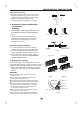
INSTALLATION INSTRUCTIONS 1. Wall-mounted type Selecting installation place More than 15cm Read completely, then follow step by step. Indoor unit More than 12cm Do not expose the indoor unit to heat or steam. More than 12cm Select a place where there are no obstacles in front or around the unit. Make sure that condensation drainage can be conveniently routed away. More than 2.3m Do not install near a doorway. Fig.1 Ensure that the space on the left and right of the unit is more than 12cm.
INSTALLATION INSTRUCTIONS Tools needed for installation: Level gauge Screwdriver Electric drill,Hole core drill (φ65mm) Flaring tool set Specified torque wrenches: 1.8kgf.m, 4.2kgf.m, 5.5kgf.m, 6.6kgf.m(different depending on model No.
INSTALLATION INSTRUCTIONS Mor e tha 2 n 12 cm M or e th an More than 15cm 1 12 cm More 1 2 c m th a n 3 M or e th an 12 cm Ai r fil te r A ir fi lt er Ai r fil te r Ai r fil te r 4 5 Remote Remote controller Remote controller controller Mor e tha Mor n 12 e tha cm n 12 cm Mo 10c re tha m n Air out More than 60cm Remote controller 6 tha re Mo cm 0 3 n A A A ir fi lt r ir fi lt e er Mo re th a 0 n2 0c Mo 60 re th cm an m C B Loop a connective cable Remote controlle
INSTALLATION INSTRUCTIONS Indoor unit installation(wall-mounted type) Correct orientation of Installation Plate 1. Fit the Installation Plate 1. Fit the installation plate horizontally on structural parts of the wall with spaces around the installation plate. 2. If the wall is made of brick, concrete or the like, drill five or eight 5mm diameter holes in the wall.Insert Clip anchor for appropriate mounting screws. 3. Fit the installation plate on the wall with five or eight type ?A? screws. Fig.
INSTALLATION INSTRUCTIONS 2. Drill a hole in the wall Wall 1. Determine hole positions according to the diagramdetailed in Fig.5. Drill one (1) hole (φ65mm) slanting slightly to outdoor side. 2. Always use wall hole conduit when drilling metal grid, metal plate or the like. Outdoor 5-7mm Indoor Fig.6 3. Connective Pipe and Drainage Installation Drainage 1. Run the drain hose sloping downward. Do not install the drain hose as illustrated in Fig.7. Do not put the end of drain hose into water.
INSTALLATION INSTRUCTIONS 4. Indoor unit installation 1. Pass the piping through the hole in the wall. 2. Put the upper claw at the back of the indoor unit on the upper hook of the installation plate, move the indoor unit from side to side to see that it is securely hooked (see Fig.12). 3. Piping can easily be made by lifting the indoor unit with a cushioning material between the indoor unit and the wall. Get it out after finish piping. 4.
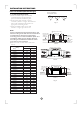
INSTALLATION INSTRUCTIONS 2.1 Selecting installation site 2. Four-way cassette type When the conditions in the ceiling are exceeding 300C / 860F and a relative humidity of 80%, or when fresh air is inducted into the ceiling, an additional insulation is required (minimum 10 mm / 0.4in thickness, polyethylene foam). ACCESSORIES Check if the following accessories are included with your unit.
INSTALLATION INSTRUCTIONS Relation of ceiling opening to unit and installation hook position. 5 4 1000/39.37in 1000/39.37in 1000/39.37in 1 Fig.13 3 647/25.47in 2 523/20.59in 1 570/22.44in 2 1) Preparations before installation 2 1000/39.37in 2500/98.43in 260/10.24in 290/11.4in 2.2 1 2 545/21.45in 570/22.44in 3 647/25.47in Fig.15 7 1000/39.37in 70/2.76in 1000/39.37in 8 15/0.59in 6 600/23.62in 20/0.79in 15/0.59in 20/0.
INSTALLATION INSTRUCTIONS 2.3 NOTE: Installation is possible with a ceiling dimension of 600 mm / 23.62in(marked with * ) . However, to achieve a ceiling-panel overlapping dimension of 15 mm / 0.59in, the spacing between the ceiling and the unit should be 20 mm / 0.79in or less.If the spacing between ceiling and the unit is over 20 mm / 0.79in, attach sealing material in the part or recover the ceiling.
INSTALLATION INSTRUCTIONS 2.4 DRAIN PIPING WORK Installation of drain piping 1 Install the drain piping as shown in figure below and take measures against condensation. Improperly rigged piping could lead to leaks and eventually wet furniture and belongings. 2 3 1-1.5m 3~5ft 1 2 3 1 2 Paper pattern for installation (on some models) Center of the ceiling opening Screws (supplied with the decoration panel) √ Fig.20 3) Adjust the unit to the right position for installation.
INSTALLATION INSTRUCTIONS How to perform piping Drain piping connections Do not connect the drain piping directly to sewage pipes that smell of ammonia. The ammonia in the sewage might enter the indoor unit through the drain pipes and corrode the heat exchanger. Keep in mind that it will become the cause of getting drain pipe blocked if water collects on drain pipe. 2 3 6 5 4 ≤750/29.5in ≤300/11.8in 5 220/8.7in ≤530/21in 0~75 0~2.95in 1 1~1.
INSTALLATION INSTRUCTIONS 2.5 INSTALLATION OF THE DECORATION PANEL - After installing the decoration panel, ensure that there is no space between the unit body and decoration panel. Otherwise air may leak through the gap and cause dewdrop. Detach the intake grille. - Slide the 2 grille hooks toward the middle of the decoration panel. 1 Fig.27 1 2 √ × 2 Fig.31 Fig.30 Intake grille Grille hook Mount the intake grille.
INSTALLATION INSTRUCTIONS 3. Duct & Ceiling type Installation precautions 1. Determine the moving route. 2. Move the unit in original state. 3. Make sure to do electric insulation according to relevant electric standard in case the unit is installed on metal part of building. 4. Please keep away from the following places, or malfunction may be caused. (if unavoidable, please consult the professionals): A. There is mineral oil like the oil of cutting machine. B. There is much salty air. (Near the coast) C.
INSTALLATION INSTRUCTIONS Installation of unit Install φ10 (4 pieces)hanging screw bolt Determine the location of hanging screw bolt following Fig.40. Make sure to use the hanging screw bolt of φ10. The treatment to the ceiling varies from construction; please consult the professionals for details. 1) Treatment to ceiling---make sure to consolidate the roof beam for possible vibration to keep the ceiling horizontal. 2) Please cut off the roof beam.
INSTALLATION INSTRUCTIONS The position of hanging bolts Dimension and air outlet size Air inlet size Air filter Position size of descensional ventilation opening Air filter Electric control box Size of mounted hook Electric control box Fig.
INSTALLATION INSTRUCTIONS Air outlet opening size Outline dimension A B E H I J K Size of mounted lug F G <12000Btu/h 700 210 635 570 65 18000Btu/h 920 210 635 570 65 493 713 35 35 119 595 200 119 815 200 80 80 740 350 960 350 >24000Btu/h 920 270 635 570 65 713 35 179 815 260 20 960 350 C D Air return opening size L M How to adjust the air inlet direction?(From rear side to under-side.) 1. 2. Take off ventilation panel and flange, cut off the staples at side rail.
INSTALLATION INSTRUCTIONS Drainpipe installation 1. Indoor unit drainpipe installation Piping, insulation material Piping Fig.42 Hard PVC pipe Insulation material Cellular polyethylene, thicker than 6mm No space Drainage See Fig.42 Hard PVC pipe Heat insulation material Seal the insulation material Heat insulation Please do heat insulation on piping joint. Bind the contact insulation part between the unit and installation location with bandage. Fig.
INSTALLATION INSTRUCTIONS CAUTION 1.5m~2m Supporting Unit The drain pipe as well as the connection part of indoor unit must be heat insulated, or condensate will occur. Please connect the pipe with horny PVC bond and make sure there is no leakage. Do not impose the pressure on connecting part of drainpipe. The gradient downwards of drain pipe should be over 1/100, and do not bend the drain pipe. Pull the drain pipe transversely within 20m.
INSTALLATION INSTRUCTIONS 4. Ceiling and Floor type 4.1 Accessories Name of Accessories Q'ty Qutline Remote Controller & Its Frame (on some models) Usage Owner's manual 1 InstallatiOn manual 1 Hook 2 For wall mounting instal lation Hanging ar m 2 For ceiling installation Magnetic ring 1 For wire connetion 1. Remote controller..................1 (This manual) 2. Frame...................................1 3. Mounting screw (ST2.9x10-C-H).....................2 4..
INSTALLATION INSTRUCTIONS 4.2 Indoor unit installation 4. For original concrete bricks Use embedding screw bold, crock and stick harness (Refer to Fig.49-4). 1. Installing 10 hanging screw bolts (4 bolts). Please refer to the following figure for the distance measurement between the screw bolts. Please install with 10 hanging screw bolts. The handling to the ceiling varies from the constructions, consult the construction personnels for the specific procedures.
INSTALLATION INSTRUCTIONS 1. Fix the hook with tapping screw onto the wall. (Refer to Fig.49-7) 2. Hang the indoor unit on the hook. 20 ~25mm 2. Location the hanging arm on the hanging screw bolt. (Refer to Fig.49-10) Prepare the mounting bolts on the unit. (Refer to Fig.49-11) Hook 8-13mm Screw nut Washer Hanging screw bolt Hanging arm Tapping screw Mounting bolt (Max.40mm) Fig.49-11 Fig.49-10 Washer 3. Hang the unit on the hanging arm by sliding backward.
INSTALLATION INSTRUCTIONS . This manual is subject to changes due to technological improvement without further notices. 4.5 The Dimension of the Unit Unit:mm Capacity 12-18 A B C 990 660 206 D 505 F G H 907 200 203 E 506 Mounting screw B ST2.9x10-C-H SET TEMPERATURE?? OC) Note:The dimension of 12000Btu/h and 18000Btu/h are the same. AUTO COOL DRY HEAT FAN HIGH MED LOW TEMP. MODE ON/OFF FAN SPEED SWING ECONOMIC TIMER ON RESET LOCKTIMER OFF 5.
INSTALLATION INSTRUCTIONS Hang the indoor unit on the hook. (The bottom of body can touch with floor or suspended, but the body must install vertically. ) CAUTION Keep indoor unit, outdoor unit, power supply wiring and transmission wiring at least 1 meter away from televisions and radios. This is to prevent image interference and noise in those electrical appliances. (Noise may be generated depending on the conditions under which the electric wave is generated, even if 1 meter is kept.
INSTALLATION INSTRUCTIONS 1. Drill a hole in the wall (suitable just for the size of the wall conduit), then set on the fittings such as the wall conduit and its cover. 2. Bind the connecting pipe and the cables together tightly with binding tapes. Pass the bound connecting pipe through the wall conduct from outside. Be careful of the pipe allocation to do on damage to the tubing. 3. Connect the pipes. Refer to "How to Connect the pipes" for details. 4. Expel the air with a vacuum pump.
INSTALLATION INSTRUCTIONS When the declivity of the drain pipe downwards is over 1/100, there should not be any winding. The total length of the drain pipe when pulled out traversely shall not exceed 20m, when the pipe is over long, a prop stand must be installed to prevent winding. Refer to the figures on the right for the installation of the pipes. Be sure to locate the power wiring and the signal wring well to avoid cross-disturbance.
INSTALLATION INSTRUCTIONS Outdoor unit installation Outdoor installation precaution Install the outdoor unit on a rigid base to prevent increasing noise level and vibration. Determine the air outlet direction where the discharged air is not blocked. In the case that the installation place is exposed to strong wind such as a seaside, make sure the fan operating properly by putting the unit lengthwise along the wall or using a dust or shield plates.
REFRIGERANT PIPE CONNECTION Drain joint installation NOTE: The drain joint differ from appliance to appliance. Fit the seal into the drain joint, then insert the drain joint into the base pan hole of outdoor unit, 。 rotate 90 to securely assemble them. Connecting the drain joint with an extension drain hose (Locally purchased), in case of the water draining off the outdoor unit during the heating mode.
ELECTRICAL WORK Tightening Connection Align the center of the pipes. Sufficiently tighten the flare nut with fingers, and then tighten it with a spanner and torque wrench as shown in Fig.58 & 59 Outer diam. Flare nut Pipings Fig.58 Tightening Additional tightening torque(N.cm) torque(N.cm) 1600 (163kgf.cm) 9.52 1500 (153kgf.cm) 2500 (255kgf.cm) 12.7 3500 (357kgf.cm) 3600 (367kgf.cm) 6.35 Indoor unit tubing 2600 (265kgf.
ELECTRICAL WORK Wiring connection NOTE: Before performing any electrical work, turn off the main power to the system. CAUTIONS Minimum norminal cross-sectional area of conductors: Rated current of appliance Nominal cross-sectional area (mm 2) (A) 0.75 >3 and <6 Do not touch the capacitor even if you have disconnected the power for there is still high voltage power on it, or electric shock hazard may occur.
ELECTRICAL WORK IMPORTANT: Connect the connective cables to the terminals as identified with their respective matched numbers on the terminal block of indoor and outdoor units. For example, see the following US models: Terminal L1(A) of outdoor must connect with terminal L1 on the indoor unit.
ELECTRICAL WORK NOTE: please refer to the following figures,if the client want wire by themselves.
ELECTRICAL WORK L1 L2 1(B) 2(B) 3(B) 1(C) 2(C) 3(C) 1(D) 2(D) 3(D) 1(A) 2(A) 3(A) POWER POWER 1 2 3 1 2 3 1 2 3 1 2 3 TO A TO B TO C TO D 1 2 3 1 2 3 1 2 3 1 2 3 TO A TO B TO C TO D Model E L1 L2 L1(B) L2(B) S(B) L1(C) L2(C) S(C) L1(D) L2(D) S(D) L1(A) L2(A) S(A) L1 L2 Model F 1(B) 2(B) 3(B) 1(C) 2(C) 3(C) 1(D) 2(D) 3(D) 1(A) 2(A) 3(A) POWER L1 L2 S L1 L2 S L1 L2 S L1 L2 S TO A TO B TO C TO D Model G One-five models: L N L(C) N(C) S(C) L(D) N(D) S(D) L(E) N(E) S(E)
ELECTRICAL WORK 1(A) 2(A) 3(A) 1(B) 2(B) 3(B) L1 L2 L1 L2 1(C) 2(C) 3(C) 1(D) 2(D) 3(D) 1(E) 2(E) 3(E) L1(A) L2(A) S(A) L1(B) L2(B) S(B) L1(C) L2(C) S(C) L1(D) L2(D) S(D) L1(E) L2(E) S(E) POWER POWER 1 2 3 TO A 1 2 3 1 TO B 2 3 1 TO C 2 3 TO D 1 1 2 3 1(A) 2(A) 3(A) 1(B) 2(B) 3(B) 3 1 2 3 1 TO B 2 3 TO C 1 2 3 TO D 1 2 3 TO E Model F Model E L1 L2 2 TO A TO E 1(C) 2(C) 3(C) 1(D) 2(D) 3(D) 1(E) 2(E) 3(E) POWER L1 L2 S L1 L2 S L1 L2 S L1 L2 S L1 L2 S TO A
AIR PURGING Air purging Air and moisture in the refrigerant system have undesirable effects as indicated below: ● Pressure in the system rises. ● Operating current rises. ● Cooling or heating efficiency drops. ● Moisture in the refrigerant circuit may freeze and block capillary tubing. ● Water may lead to corrosion of parts in the refrigeration system.
AIR PURGING 4. Operate the vacuum pump to evacuate. After starting evacuation, slightly loose theflare nut of the Lo valve on the gas pipe side and check that the air is entering(Operation noise of the vacuum pump changes and a compound meter indicates 0 instead of minus) 5. After the evacuation is complete, fully close the handle Lo of the manifold valve and stop the operation of the vacuum pump. Make evacuation for 15 minutes or more and check that the compound meter indicates -76cmHg (-1x10⁵Pa). 6.
TEST RUNNING ● Gas leak check 1. Soap water method: Apply a soap water or a liquid neutral detergent on the indoor unit connection or outdoor unit connections by a soft brush to check for leakage of the connecting points of th piping. If bubbles come out, the pipes have leakage. Indoor unit check point E Outdoor unit check point 2. Leak detector Use the leak detector to check for leakage. CAUTION A: Lo packed valve B: Hi packed valve C and D are ends of indoor unit connection.
The Klimaire logo is a registered Trademark of Klimaire Products inc. Copyright 2016 Klimaire Products inc. . 2190 NW 89 Place, Doral, FL 33172 - USA Tel: (305)594-4972 Fax (305) 499 4378 www.klimaire.com sales@klimaire.com The design and specifications are subject to change without prior notice for product improvement.