Multi outdoor units SERVICE MANUAL Multi - Zone heat pump units Model Numbers: KMIR218-H221 / KMIR327-H217 / KMIR436-H217 / KMIR545-H219 Table of Contents 1. 2. 3. 4. 5. 6. 7. 8. 9.
CONTENTS 1. Indoor Unit Combination .......................................................................................................................................... 4 2. Suggested Indoor Unit Model Numbers ...................................................................................................................5 3. Dimension Of Outdoor Unit...................................................................................................................................... 6 4.
1.
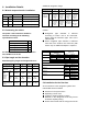
18+18+24 12+12+18+18 9+9+9+9 9+9+9+9+9 9+9+9+12 9+9+9+9+12 9+9+9+18 9+9+9+9+18 9+9+9+24 9+9+9+9+24 9+9+12+12 KSIM545-H219 1 drives 5 48k Btu 9+9+12+18 9+9+9+12+12 KSIM545-H219 1 drives 5 48k Btu 9+9+9+12+18 9+9+12+24 9+9+9+18+18 9+9+18+18 9+9+12+12+12 9+9+18+24 9+9+12+12+18 9+12+12+12 9+12+12+12+12 9+12+12+18 9+12+12+12+18 9+12+12+24 12+12+12+12+12 9+12+18+18 9+18+18+18 12+12+12+12 12+12+12+18 12+12+12+24
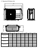
2. Dimension Of Outdoor Unit A B D Model W D H W1 A B mm 845 363 702 923 540 350 inch 33.3 14.3 27.6 36.0 21.3 13.8 mm 946 410 810 1034 673 403 inch 37.2 16.5 31.9 40.6 26.5 15.9 mm 946 410 810 1034 673 403 inch 37.2 16.5 31.9 40.6 26.5 15.9 mm 952 415 1333 1045 634 404 inch 37.5 16.3 52.5 41.1 25.0 15.
3. Refrigerant Cycle Diagram 4.1 Refrigeration circuit drawing of inverter 1 drives 2 type INDOOR OUTDOOR LIQUID VALVE A EXV A CAPILIARY A CHECK VALVE LIQUID VALVE B EXV B CAPILIARY B CAPILIARY TUBE HEAT EXCHANGE (EVAPORATOR) T4 Ambient temp. sensor T1 Room temp. sensor T3 Condenser temp. sensor HEAT EXCHANGE (CONDENSER) T2B-A Evaporator T2 Evaporator temp. sensor middle GAS VALVE A temp. sensor outlet 4-WAY VALVE GAS VALVE B T2B-B Accumulator T5 Discharge temp.
4.3 Refrigeration circuit drawing of inverter 1 drives 4 type INDOOR OUTDOOR LIQUID VALVE A LIQUID VALVE B EXV A CAPILIARY A EXV B CAPILIARY B CHECK VALVE LIQUID VALVE C LIQUID VALVE D HEAT EXCHANGE (EVAPORATOR) EXV C CAPILIARY C EXV D CAPILIARY D CAPILIARY TUBE T4 Ambient temp. sensor T1 Room temp. sensor T3 Condenser temp. sensor HEAT EXCHANGE (CONDENSER) T2B-A Evaporator GAS VALVE A T2 Evaporator temp. sensor middle GAS VALVE B GAS VALVE C GAS VALVE D temp.
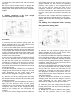
Additional refrigerant charge 4. Installation Details 5.1 Wrench torque sheet for installation Outside diameter Torque Additional tightening torque mm inch N.cm N.cm Ф6.35 1/4 1500(153kgf.cm) 1600(163kgf.cm) Ф9.52 3/8 2500(255kgf.cm) 2600(265kgf.cm) Ф12.7 1/2 3500(357kgf.cm) 3600(367kgf.cm) Chargeless pipe length (m) Additiona g l refrigeran t charge oz 1 drive 2 15 (49.2ft) 15 x (length for all rooms 15) 0.161 x(length for all rooms – 49.2) 1 drive 3 22.5 (73.
will create an acid that will damage the motor windings and components. Therefore, the indoor units and the pipes between indoor and outdoor units must be leak tested and evacuated to remove gas and moisture from the system. Gas leak check (Soap water method): Apply soap water or a liquid neutral detergent on the indoor unit connections or outdoor unit connections with a soft brush to check for leakage of the connecting points of the piping. If bubbles come out, the pipes have leakage.
7). Mount the valve stems nuts and the service port cap. Be sure to use a torque wrench to tighten the service port cap to a torque 18N·m (13.27 ft·lbs). Always leak check after servicing the refrigerant system. 3. Adding refrigerant if the pipe length exceeds chargeless pipe length the system close the low pressure valve on the gauge manifold set and record the operating pressure. The system is now charged and the unit can be shut off.
manifold set to start charging the unit with liquid refrigerant, keep track of the refrigerant being added to the system (do not overcharge the system). 7) Once the correct charge has been added to the system close the low pressure valve on the gauge manifold set and record the operating pressure. The system is now charged and the unit can be shut off.
5.7 Evacuation after servicing the outdoor unit refrigeration circuit 1. Evacuation of the complete refrigeration circuit, Indoor and outdoor unit. Procedure: 1). Confirm that both the 2-way and 3-way valves are set to the opened position. 2). Connect the vacuum pump to 3-way valve’s service port. 3). Evacuation for approximately one hour. Confirm that the compound meter indicates 0.1Mpa (500 Microns / 29.9 in,hg). 4).
6.3 Main Protection 6.3.1 Three Minutes Delay at restart for compressor. ---- 1min delay for the 1st time start-up and 3 minutes delay for others. 6.3.2 Temperature protection of compressor discharge. When the compressor discharge temperature is getting higher, the running frequency will be limited as below rules: ----If 221 ºF(105 ºC)≦T5<230 ºF (110ºC), keep the current frequency. ----If the temperature increase and T5≧ 230 ºF (110 ºC), decrease the frequency to the lower level every 2 minutes till to F1.
Note: if the low voltage protection occurs and not resumes within 3min, it will keep the protection always after restart the machine. ºF 59 57 HeatT4Zone4I 6.3.6 Compressor current limit protection 50 48 HeatT4Zone3I 43 41 HeatT4Zone2I Temperature interval.of current limit is same as range of T4 limited frequency. Cooling mode: HeatT4Zone1I ºF CoolT4Zone5I 122 HeatReturnI 120 The difference between limit current and quit current.
6.3.10 Oil return According to the final capacity request to confirm the operating frequency, as following table. Running rules: 1. If the compressor frequency keeps lower than setting frequency for setting time, the AC will rise the frequency to setting frequency for setting time and then resume to former frequency. 2. The EXV will keep 300p while the indoor units will keep the current running mode. If the outdoor ambient is higher than setting frequency during the oil return, the AC quit oil return. 6.
Then modify it according to T2 average (correction): 3)If the compressor cumulate running time is up to 40 minutes and T3< -11ºF (-24C) for 3 minutes. Note:Average value of T2:Sum T2 value of all indoor units)/ (indoor units number 4)If the compressor cumulate running time is up to 120 minutes and T3<-5ºF (-15ºC). Condition of ending defrosting: ºF T2 average If any one of the following items is satisfied, the defrosting will finish and the machine will turn to normal heating mode.
113 109 82 79 77 73 72 68 66 63 50 48 32 30 23 21 14 12 T3 Outdoor temperature ºF Supper high fan speed Increase fan speed increase LowCoolT3_ON High fan speed Middle fan speed LowCoolT3_Down Low fan speed LowCoolT3_OFF Supper low fan speed Keep current fan speed Decrease fan speed Fan stop Breeze fan speed F fan speed G fan speed H fan speed I fan speed 6.4.3.
starts. 3. The action priority of the EXVs is A-B-C-D-E. 4. Compressor and outdoor fan start operation only after EXV is initialized. 6.4.4.1 Cooling mode The initial open angle of EXV is depend on indoor model size, adjustment range is 100-400p. When the unit start to work for 3 minutes, the outdoor will receive indoor units( of capacity demand) T2B information and calculate the average of them.
7. Wiring Diagrams 8.1 Wiring diagram of 1 drive 2 outdoor KMIR218-H221 8.
8.
8.
8. Troubleshooting 8.1Safety Because of there are capacitors in PCB and relative circuit in outdoor unit, even shut down the power supply, electricity power still are kept in capacitors, do not forget to discharge the electricity power in capacitor. The value of resistance is about 1500 ohm to 2000 ohm .
The voltage in P3 and P4 in outdoor PCB is high voltage about 310V The voltage in P5 and P6 in outdoor PCB is high voltage about 310V 8.
★ ★ X Outdoor fan has been out of control E7 E8 ★ X Indoor fan speed has been out of control F5 —— ★ X Voltage protection P0 E5 ★ X X Temperature protection of compressor top. P1 P0 ★ ★ ★ X Outdoor unit over-current protection P2 P3 ★ ◎ X X Inverter compressor drive protection P4 —— ★ X Mode conflict P5 —— ★ flash at 2.5Hz, light, X extinguished, , ◎flash at 0.5Hz Note: Digital display is only available for duct type.
Push the switch SW1 to check the states of unit when the unit is running. The digital display tube will display the follow procedure when push SW1 each time.
8 A Indoor unit capacity demand code 9 B Indoor unit capacity demand code 10 C Indoor unit capacity demand code 11 D Indoor unit capacity demand code 12 E Indoor unit capacity demand code 13 Outdoor unit amendatory capacity demand code 14 The frequency corresponding to the total indoor units amendatory capacity demand The frequency after the frequency limit 15 16 17 The frequency sending to compressor control chip A indoor unit evaporator outlet temp.
43 Average value of T2 (Sum T2 value of all indoor units)/( number of indoor units in good connection) 44 Outdoor unit fan motor state Off:0, High speed:1, Med speed:2, Low speed:3 Breeze:4, Super breeze:5 45 The last error or protection code 00 means no malfunction and protection 46 F indoor unit capacity 47 F Indoor unit capacity demand code 48 F indoor unit evaporator outlet temp.(T2BF) 49 F indoor unit room temp.(T1F) 50 F indoor unit evaporator temp.
8.3.
8.4 Diagnosis and Solution 8.4.1 Indoor unit trouble shooting 8.4.1.1 Indoor EEPROM malfunction diagnosis and solution. Malfunction decision conditions PCB main chip does not receive feedback from EEPROM chip ● Installation mistake ● PCB faulty Trouble shooting: Shut off the power supply and turn it on 1 minute later. Is it still displaying the error code? Yes If the EEPROM chip is welded on PCB, replace the PCB directly.
8.4.1.2 Communication malfunction between indoor and outdoor units diagnosis and solution. Malfunction decision conditions Supposed causes Indoor unit does not receive the feedback from outdoor unit during 120 seconds.
Indoor / outdoor units communication error Start: Power off , then Power on the A/C by the Breaker. (reconnect the power wire). Is it still displaying the error code? Yes Check wiring on the outdoor and indoor terminal follow the wiring diagram. Is all connecting correctly? No Reconnect the wiring No Reconnect the wiring Yes Turn on all indoor unit by remote controller.
Pic 1: Use a multimeter to test the DC voltage between L2 port and S port of outdoor unit. The red pin of multimeter connects with L2 port while the black pin is for S port. When AC is normal running, the voltage will move alternately between positive value and negative value.
PIC3: Main board LED when power on and unit standby. PIC 4: Check point button, press 1 time for check how many indoor units are connected.
8.4.1.3 zero-crossing signal error diagnosis and solution. Malfunction decision conditions Supposed causes When PCB does not receive zero crossing signal feedback for 4 minutes or the zero crossing signal time interval is abnormal. ● Connection mistake ● PCB faulty Trouble shooting: Check if the connections and power supply is normal? Yes Indoor main PCB is defective. Replace indoor main PCB. No Correct the connections. Turn on the unit when the power supply is good.
8.4.1.4 Indoor fan speed has been out of control diagnosis and solution. Malfunction decision conditions When indoor fan speed keeps too low (300RPM) for certain time, the unit will stop and the LED will display the failure. ● Wiring mistake Supposed causes ● Fan ass’y faulty ● Fan motor faulty ● PCB faulty Trouble shooting: Shut off the power supply and turn it on 1 minute later. Is it still displaying the error code? No The unit operates normally.
Index 1: 1: Indoor AC fan motor Power on and set the unit running in fan mode at high fan speed. After running for 15 seconds, measure the voltage of pin1 and pin2. If the value of the voltage is less than 100V (208~240V power supply)or 50V(115V power supply), the PCB must have problems and need to be replaced. 2. Indoor DC fan motor (control chip is inside fan motor) Power on and when the unit is in standby, measure the voltage of pin1-pin3, pin4-pin3 in fan motor connector.
8.4.1.5 Open or short circuit of temperature sensor diagnosis and solution. Malfunction decision conditions If the sampling voltage is lower than 0.06V or higher than 4.94V, the LED will display the failure. ● Wiring mistake Supposed causes ● Sensor faulty ● PCB faulty Trouble shooting: Check the connections between temperature sensor and PCB. Are the connections good? No Correct the connections.
8.4.1.6 IPM module or IGBT over-strong current protection diagnosis and solution. Malfunction decision conditions Supposed causes Trouble shooting: When the voltage signal that IPM send to compressor drive chip is abnormal, the display LED will show “P6” and AC will turn off.
IPM module protection Check whether the voltage range of P-N on IPM module is normal? DC277-356V for 18-27KBtu/h; DC277-410V for 36KBtu/h Check whether the input power supply is correct? 208-230V, 1N, 60Hz No Regulate it to correct, then check whether the system can work normally? No Yes No Yes Check whether the connecting line between main board and the IPM module is connected tightly Connect it tightly, check ok or not? No Check whether the power supply line is connected correctly and tightly C
8.4.1.7 Over voltage or too low voltage protection diagnosis and solution.
8.4.1.8 Temperature protection of compressor top diagnosis and solution. Malfunction decision conditions Supposed causes If the sampling voltage is not 5V, the LED will display the failure. ● Wiring mistake ● Over load protector faulty ● System block ● Outdoor PCB faulty Temperature protection of compressor top Whether compressor operates? Yes No Whether the connection is good? No Reconnect and retest.
8.4.1.10 Water-level alarm malfunction diagnosis and solution (For cassette / ducted) Malfunction decision conditions Supposed causes If the sampling voltage is not 5V, the LED will display the failure. ● Wiring mistake ● Water-level switch faulty ● Water pump faulty ● Indoor PCB faulty Power Power off, off, then then restart restart the the unit unit 33 minutes minutes later. later.
8.4.1.11 Mode conflict. Error Code P5 Malfunction decision conditions The indoor units cannot work cooling mode and heating at same time. Heating mode has a priority. ● Suppose Indoor unit A working in cooling mode or fan mode, and indoor unit B is set to heating mode, then A will change to off and B will work in heating mode. ● Suppose Indoor unit A working in heating mode, and indoor unit B is set to cooling mode or fan mode, then B will change to stand by and A will be no change.
8.4.2 Outdoor unit trouble shooting 8.4.2.
8.4.2.2 E2(Communication malfunction between indoor and outdoor units) error diagnosis and solution. Error Code E2 Malfunction decision conditions Supposed causes Indoor unit does not receive the feedback from outdoor unit during 120 seconds or outdoor unit does not receive the feedback from any one indoor unit during 180 seconds.
Communication malfunction between indoor and outdoor units Start: Power off , then Power on the A/C by the Breaker. (reconnect the power wire). Is it still displaying the error code? Yes Check wiring on the outdoor and indoor terminal follow the wiring diagram. Is all connecting correctly? No Reconnect the wiring No Reconnect the wiring Yes Turn on all indoor unit by remote controller.
Pic 1: Use a multimeter to test the DC voltage between L2 port and S port of outdoor unit. The red pin of multimeter connects with L2 port while the black pin is for S port. When AC is normal running, the voltage will move alternately between positive value and negative value.
Pic 2: IPM (For qua-zone) Power, Self-Check Operating PIC3: Main board LED when power on and unit standby. PIC 4: Check point button, press 1 time for check how many indoor units are connected.
8.4.2.3 E3 (Communication malfunction between IPM board and outdoor main board) error diagnosis Error Code E3 Malfunction decision conditions Supposed causes PCB main chip does not receive feedback from IPM module during 60 seconds.
Remark: Use a multimeter to test the DC voltage between black pin and white pin of signal wire The normal value should be around 5V. Use a multimeter to test the DC voltage between black pin and red pin of signal wire. The normal value should be around 12V.
8.4.2.4E4(open or short circuit of outdoor temperature sensor) diagnosis and solution F1/F2/F3/F4/F5 (open or short circuit of indoor coil temperature sensor) diagnosis and solution. . Error Code E4/F1/F2/F3/F4/F5 Malfunction decision conditions If the sampling voltage is lower than 0.06V or higher than 4.94V, the LED will display the failure. ● Wiring mistake Supposed causes ● Sensor faulty ● PCB faulty Trouble shooting: Check the connections between temperature sensor and PCB.
8.4.2.5 E5 (Voltage protection) error diagnosis and solution. Error Code Malfunction decision conditions Supposed causes E5 An abnormal voltage rise or drop is detected by checking the specified voltage detection circuit. ● Power supply problems.
IPM (for dual/trizone) IPM (for quazone) P-N (for dual/tri-zone)
P-N (for qua-zone)
bridge rectifier (for dual/tri-zone) bridge rectifier (for qua-zone)
Remark: Measure the DC voltage between + and - port. The normal value should be 190V~250V.
8.4.2.7 E8 (Outdoor fan speed has been out of control) diagnosis and solution Error Code E8 Malfunction decision conditions When outdoor fan speed keeps too low (300RPM) or too high(2400RPM) for certain time, the unit will stop and the LED will display the failure. ● Wiring mistake ● Fan ass’y faulty ● Fan motor faulty ● PCB faulty Supposed causes Trouble shooting: Power Power off, off, then then restart restart the the unit 3 minutes later. unit 3 minutes later.
1. DC fan motor(control chip is inside fan motor) Power on and when the unit is in standby, measure the voltage of pin1-pin3, pin4-pin3 in fan motor connector. If the value of the voltage is not in the range showing in below table, the PCB must have problems and need to be replaced. DC motor voltage input and output NO. Color Signal Voltage 1 Red Vs/Vm 200~380V 2 --- --- --- 3 Black GND 0V 4 White Vcc 13.5~16.5V 5 Yellow Vsp 0~6.5V 6 Blue FG 13.5~16.
8.4.2.8 P0 (Temperature protection of compressor top) error diagnosis and solution. Error Code Malfunction decision conditions Supposed causes P0 If the sampling voltage is not 5V, the LED will display the failure.
8.4.2.9 P1 (High pressure protection) error diagnosis and solution. Error Code Malfunction decision conditions Supposed causes Trouble shooting: P1 If the sampling voltage is not 5V, the LED will display the failure.
High High pressure pressure protection protection Whether Whether the the wiring wiring between between the the high high pressure pressure switch switch and and main main control control board board is is connected connected well well or or correctly correctly No Connect Connect itit well well Yes Whether Whether the the high high pressure pressure protector protector is is broken broken Method: Method: Disconnect Disconnect the the plug. plug.
8.4.2.10 P2 (Low pressure protection) error diagnosis and solution. Error Code Malfunction decision conditions Supposed causes Trouble shooting: P2 If the sampling voltage is not 5V, the LED will display the failure.
Low Low pressure pressure protection protection Whether Whether the the wiring wiring between between the the low low pressure pressure protector protector and and main main control control board board is is connected connected well well or or correctly correctly No Connect Connect itit well well Yes Whether Whether the the low low pressure pressure protector protector is is broken broken Method: Method: Disconnect Disconnect the the plug. plug.
8.4.2.11 P3 (Current protection of compressor) error diagnosis and solution. Error Code Malfunction decision conditions Supposed causes P3 If the outdoor current exceeds the current limit value, the LED will display the failure.
8.4.2.12 P4 (Temperature protection of compressor discharge) error diagnosis and solution. Error Code Malfunction decision conditions P4 When the compressor discharge temperature(T5) is more than 239ºF (115ºC) for 10 seconds, the compressor will stop andrestart till T5 is less than 194ºF (90ºC).
8.4.2.13 P5 (High temperature protection of condenser) error diagnosis and solution. Error Code Malfunction decision conditions P5 When outdoor pipe temperature is more than 149ºF (65°C), the unit will stop, and unit runs again when outdoor pipe temperature is less than 126ºF (52°C).
8.4.2.14 P6 (IPM module protection) error diagnosis and solution. Error Code Malfunction decision conditions Supposed causes Trouble shooting: P6 When the voltage signal that IPM send to compressor drive chip is abnormal, the display LED will show “P6” and AC will turn off.
IPM module protection Check whether the voltage range of P-N on IPM module is normal? DC277-356V for 18-27KBtu/h; DC277-410V for 36KBtu/h Check whether the input power supply is correct? 208-230V, 1N, 60Hz No Regulate it to correct, then check whether the system can work normally? No Yes No Yes Check whether the connecting line between main board and the IPM module is connected tightly Connect it tightly, check ok or not? No Check whether the power supply line is connected correctly and tightly C
8.4.2.15 The cooling operation or heating operation does not operate. Supposed causes ● 4-way valve faulty Check of 4-way, please refer to part 5 in 9.5 Trouble Criterion Of Main Parts. 8.4.2.16 When cooling, heat exchanger of non-operating indoor unit frosts. When heating, non-operating indoor unit get warm. Supposed causes ● EXV faulty ● Wire and tubing connected in reverse. Check of EXV, please refer to part 6 in 9.5 Trouble Criterion Of Main Parts.
8.5 Trouble Criterion Of Main Parts. Spec.
1. 1.Temperature sensor checking Disconnect the temperature sensor from PCB, measure the resistance value with a tester. Temperature Sensors. Room temp.(T1) sensor, Indoor coil temp.(T2) sensor, Outdoor coil temp.(T3) sensor, Outdoor ambient temp.(T4) sensor, Compressor discharge temp.(T5) sensor. Measure the resistance value of each winding by using the multi-meter.
Appendix 1 Temperature Sensor Resistance Value Table (ºC-K) ºF K Ohm ºF -4 -2 0 1 3 5 7 9 10 12 14 16 18 19 21 23 25 27 28 30 32 34 36 37 39 41 43 45 46 48 50 52 54 55 57 59 61 63 64 66 115.266 68 70 72 73 75 77 79 81 82 84 86 88 90 91 93 95 97 99 100 102 104 106 108 109 111 113 115 117 118 120 122 124 126 127 129 131 133 135 136 138 108.146 101.517 96.3423 89.5865 84.2190 79.3110 74.5360 70.1698 66.0898 62.2756 58.7079 56.3694 52.2438 49.3161 46.5725 44.0000 41.5878 39.8239 37.1988 35.2024 33.
Appendix 2 Unit: ºF-K -4 -2 0 1 3 5 7 9 10 12 14 16 18 19 21 23 25 27 28 30 32 34 36 37 39 41 43 45 46 48 50 52 54 55 57 59 61 63 64 66 542.7 511.9 483 455.9 430.5 406.7 384.3 363.3 343.6 325.1 307.7 291.3 275.9 261.4 247.8 234.9 222.8 211.4 200.7 190.5 180.9 171.9 163.3 155.2 147.6 140.4 133.5 127.1 121 115.2 109.8 104.6 99.69 95.05 90.66 86.49 82.54 78.79 75.24 71.
Appendix 3: ℃ ℉ ℃ ℉ 10 48 23 74 11 50 24 76 12 52 25 78 13 54 26 80 14 56 27 82 15 58 28 84 16 60 29 86 17 62 30 88 18 64 31 90 19 66 32 92 20 68 33 94 21 70 34 96 22 72 35 98 2. Compressor check Measure the resistance value of each winding by using the tester. Resistance Value Position Blue - Red ATM150D23UFZ ATF235D22UMT ATF250D22UMT ATF310D43UMT ATQ360D1UMU ATQ420D1UMU 1.72 Ω 0.75 Ω 0.75 Ω 0.65 Ω 0.37 Ω 0.
3. IPM continuity check Turn off the power, let the large capacity electrolytic capacitors discharge completely, and dismount the IPM. Use a digital tester to measure the resistance between P and UVWN; UVW and N. Digital tester (+)Red P (-)Black N U V W Normal resistance value Normal resistance value Digital tester (+)Red U V W (+)Red ∞ (Several MΩ) (-)Black ∞ N (Several MΩ) 4. AC Fan Motor. Measure the resistance value of each winding by using the tester.
Position Resistance Value YDK70-6FB Black Red Red Yellow Yellow Blue YDK180-8GB 56Ω±8% 24.5Ω±8% (68 ºF - 20 ºC) (68 ºF - 20 ºC) 76Ω±8% 19Ω±8% (68 ºF - 20 ºC) (68 ºF - 20 ºC) 76Ω±8% 19Ω±8% (68 ºF - 20 ºC) (68 ºF - 20 ºC) YSK27-4G YSK68-4B YDK45-6B YSK25-6L YDK536FB(B) 317Ω±8% (68 ºF - 20 ºC) 145Ω±8% (68 ºF - 20 ºC) 345Ω±8% (68 ºF - 20 ºC) 627Ω±8% (68 ºF - 20 ºC) 88.5Ω±8% (68 ºF - 20 ºC) 252Ω±8% 88Ω±8% 150Ω±8% 374.
6.EXV check Disconnect the connectors.
Resistance to EXV coil Color of lead wire Normal Value Red- Blue Red - Yellow About 50Ω Brown-Orange Brown-White
Red- Blue Red - Yellow
Brown-Orange Brown-White
The Klimaire logo is a registered Trademark of Klimaire Products inc. Copyright 2016 Klimaire Products Inc. 2190 NW 89 Place, Doral, FL 33172 - USA Tel: (305)593-8358 Fax (305) 675-2212 www.klimaire.com sales@klimaire.com The design and specifications are subject to change without prior notice for product improvement. Consult with the sales agency or manufacturer for details.