
User Manual

OPERATING INSTRUCTIONS
13
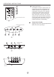
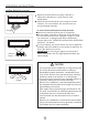
Display panel
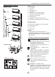
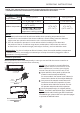
Identification of parts
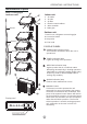
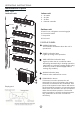
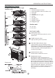
Indoor unit
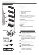
DISPLAY PANEL:
Floor and standing type(console)
7
Indoor unit
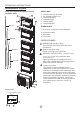
Outdoor unit
8. Drain hose, refrigerant connecting pipe
9. Connective cable
10. Stop valve
11. Fan hood
1. Indoor unit
2. Air flow louver (at air outlet)
3. Installation part
4. Air out
5. Air inlet(with air filter in it)
6. Air in
7. Remote controller
OPERATION indication lamp
This indicator illuminates when the unit is
operational.
TIMER indication lamp
Lights up during Timer operation.
AlARM indication lamp
Flashes when malfunction occurs.
DEF./FAN indication lamp
Lights up when the air conditioner starts
defrosting automatically in heating operation
(applicable to cooling & heating models only)
or fan only mode is selected(applicable to
cooling only models).
3
1
2
6
5
4
8
9
10
11
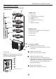
NOTE: The display window on the air
conditioner you purchased may look
like one of the following:
4
2
5
1
3
Infrared signal receiver
(1)
One-twin
One-three
One-four
One-five