
User Manual

OPERATING INSTRUCTIONS
15
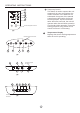
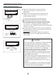
Display panel
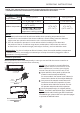
Identification of parts
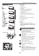
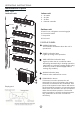
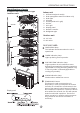
Indoor unit
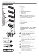
DISPLAY PANEL:
Duct / Ceiling type
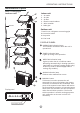
Indoor unit
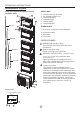
Outdoor unit
7. Drain hose, refrigerant connecting pipe
8. Connective cable
9. Stop valve
10. Fan hood
1. Air outlet
2. Air inlet
3. Air filter
4. Electric control cabinet
5. Wire controller
6. Drain pipe
OPERATION indication lamp
This indicator illuminates when the unit is
operational.
TIMER indication lamp
Lights up during Timer operation.
AlARM indication lamp
Flashes when malfunction occurs.
DEF./FAN indication lamp
Lights up when the air conditioner starts
defrosting automatically in heating operation
(applicable to cooling & heating models only)
or fan only mode is selected(applicable to
cooling only models).
7
8
9
10
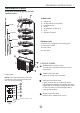
Infrared signal receiver
Digital display window
MANUAL OPERATION TIMER DEF./FAN ALARM
MANUAL button
This button is used to operate the unit
temporarily in case you misplace the remote
controller or its batteries are exhausted. One
press of the manual control button will lead to
the forced AUTO operation. If press the button
twice within five seconds, the unit will operate
under forced COOL operation. The forced
COOL operation is used for testing purposes
only, please do not choose it unless it is
necessary.
One-twin
One-three
One-four
One-five