
Installation Manual
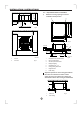
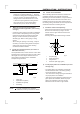
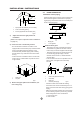
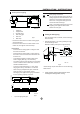
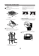
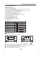
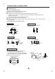
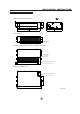
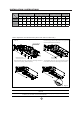
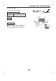
Table Of Contents

13
INSTALLATION INSTRUCTIONS
- Connect the drain hose to the drain raising pipes,
and insulate them.
- Connect the drain hose to the drain outlet on the
indoor unit, and tighten it with the clamp.
How to perform piping
Precautions
than 530 mm/20.87in.
- Install the drain raising pipes at a right angle to
the indoor unit and no more than 300 mm/11.8in
from the unit.
- To prevent air bubbles, install the drain hose
level or slightly tilted up (<75 mm/2.95in).
- The incline of drain hose should be 75 mm/2.95in
or less so that the drain socket does not have to
withstand additional force.
- To ensure a downward slope of 1:100, install
hanging bars every 1m/3.28ft to 1.5 m/4.92ft.
- When unifying multiple drain pipes, install the
pipes as shown in figure below. Select
converging drain pipes whose gauge is suitable
for the operating capacity of the unit.
- Install the drain raising pipes at a height of less
1 Ceiling slab
2 Hanger bracket
3 Adjustable range
4 Drain raising pipe
5 Drain hose
6 Metal clamp
1 T-joint converging drain pipes
0-530/20.87 in
100
1
1
Drain piping connections
Do not connect the drain piping directly to
sewage pipes that smell of ammonia. The
ammonia in the sewage might enter the
indoor unit through the drain pipes and
corrode the heat exchanger.
Keep in mind that it will become the cause
of getting drain pipe blocked if water
collects on drain pipe.
Unit: mm
Unit: mm
Add approximately 1L of water gradually through
the air discharge outlet.
Method of adding water (see the figure below)
Testing of drain piping
After the piping work is finished, check if drainage
flows smoothy.
1 Plastic watering can(tube should be about 100 mm long)
2 Water-receiver
/3.93in
When exlectric wiring work is finished, check
drainage flow during COOL running.
Unit: mm
1
2
Fig.25
Fig.24
Fig.26
1
2
0~75
5
1~1.5m
≤300/11.8in
6
5
4
3
220/8.7in
≤750/29.5in
0~2.95in
≤530/21in
3~5ft
1 2
≥100/3.93in
Fresh air intake (φ65/2.56in)
106/4.17in
106/4.17in
75/2.95in
65/2.56in
3.93 in